Debugging a run
You use the single-run debugger to debug a run after you execute it in Foretify. You can also launch the single-run debugger from Foretify Manager in order to investigate runs from your test suite results.
Use the single-run debugger
Foretify Developer is a web-based application that opens in your default browser.
To use the single-run debugger in Foretify:
-
Load a test.
-
Prepare the test.
-
Run the test.
-
Optionally, debug load-time issues.
-
In the Debug Run tab, debug the test.
See also how to preview a run, view the map, and inspect linter violations.
To use the single-run debugger in Foretify Manager:
In Foretify Manager, you can debug a run using one of the following methods:
-
To launch the debugger from the main project view, select the Runs tab and click the run you want to debug.
-
To launch the debugger from Triage, in the Triage Runs table, click the "Open Triaged Run in New Tab" icon for the run you want to debug. You can also run the debugger on the matching run of the previous test suite result by clicking the "Open Previous Run in New Tab" icon.
Debug a run
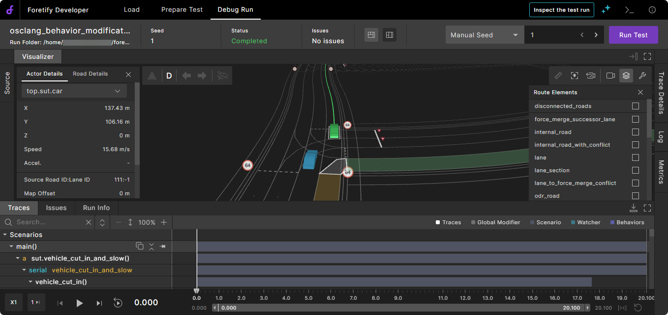
The Debug Run tab displays the run in various ways:
- The Visualizer displays the actors on the map.
- The Traces view displays the values of the traced parameters, as well as intervals—visualizations that represent abstract data over a time span. See Debugging in Traces view.
- Logs are displayed in the Log tab on the right. To change the units displayed in logs, see Display unit options.
- Any Issues that occurred during the run are listed in the Issues frame below the Visualizer. See how to get help on an issue.
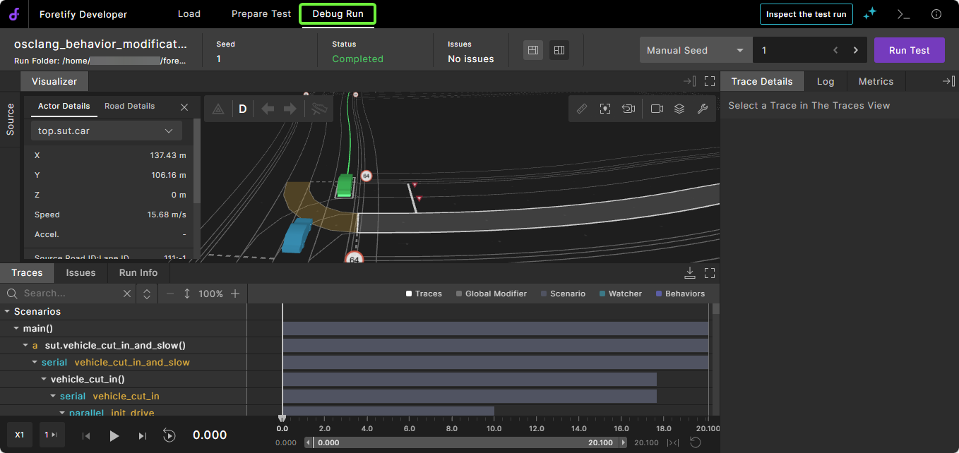
The Visualizer, Issues, and Traces frames are synchronized to the timeline displayed at the bottom of Foretify Developer. For example, if you select an issue or move the cursor in the Traces view, the other views change accordingly.
Note
You can maximize or minimize most frames within the Debug Run tab using the Maximize and Minimize icons at the top right corner of the frame.
Customize the debugger layout
The Visualizer, Traces, and other panes in the Single Run Debugger can each be resized, expanded, or collapsed to tailor the layout to your current task. Your preference is saved and persists.
Adjust individual panes
- Click the Maximize
 icon for the pane to occupy maximum available screen space. Click the
  icon to restore it to the previous arrangement.
 - Use the Expand
 and Minimize
  icons to show or hide individual panes.
Layout presets
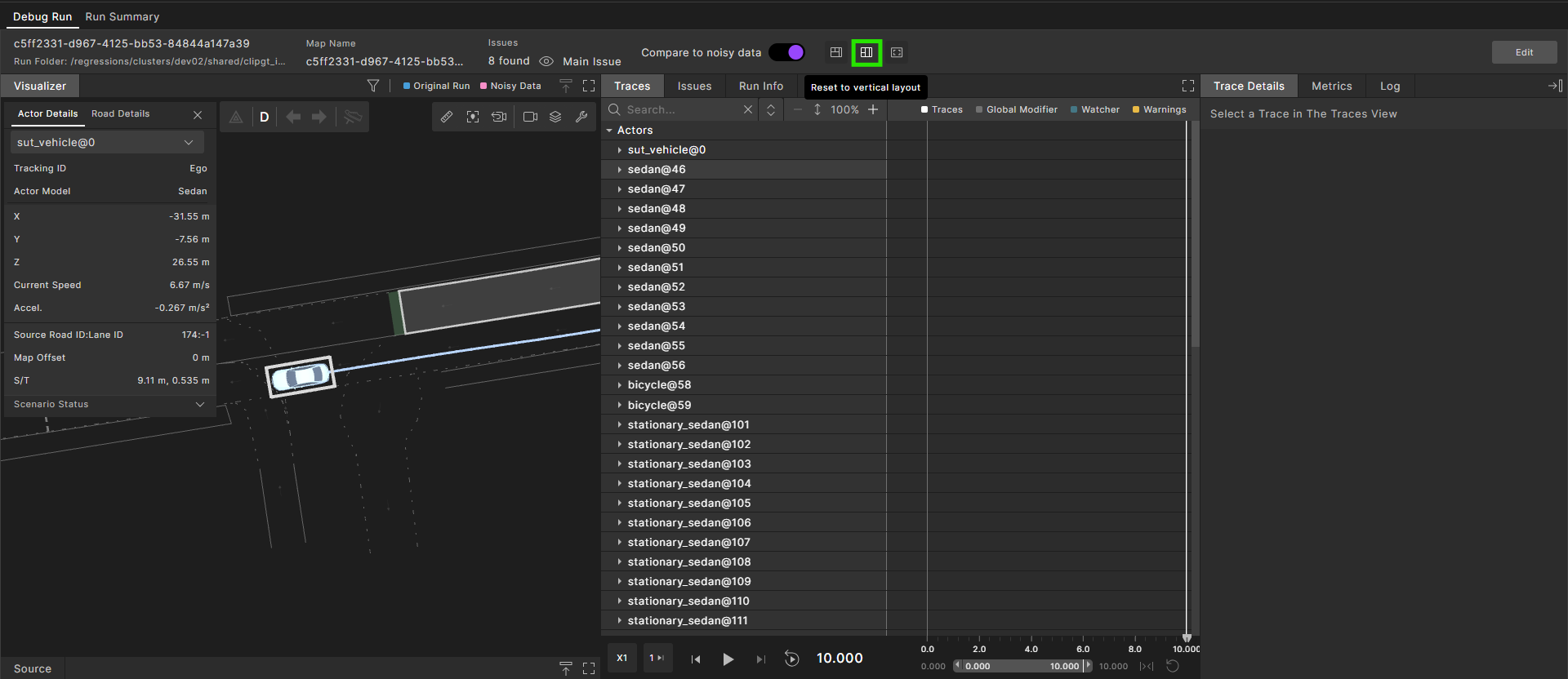
Single Run Debugger offers three preconfigured layouts suitable for the most frequent tasks. Selecting a layout preset returns you to its predefined arrangement instantly.
-
Horizontal layout

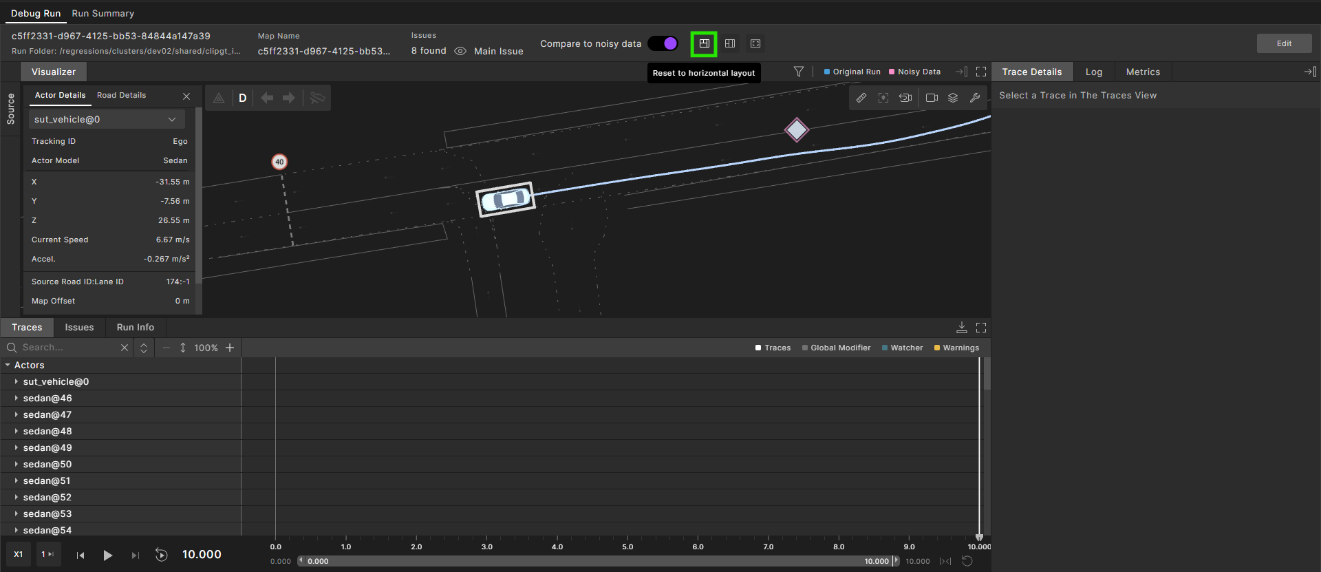
-
Vertical layout

-
Visualizer-focused layout

Maximizes the Visualizer and tucks the other panes out of view. Expand any pane on demand when you need it.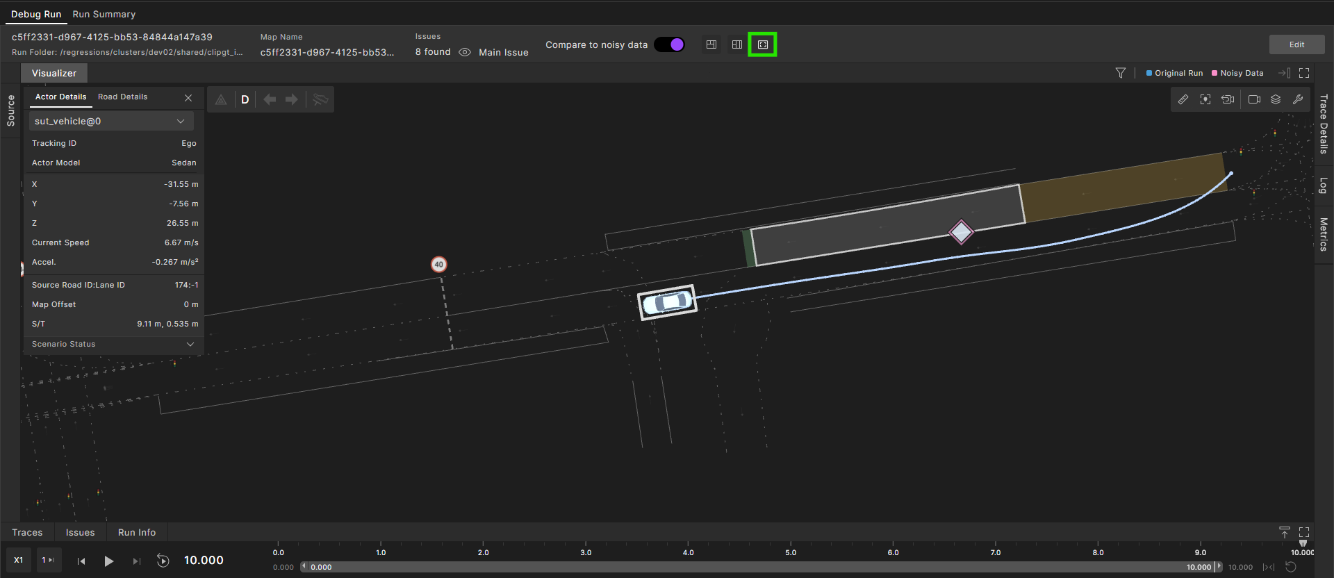
Get help on an issue
Foretify has predefined, global checkers that report an issue if an actor (usually the SUT or another vehicle) did not behave as expected during a run. In addition, Foretify arranges all issues by category and severity type, displaying the issue with the greatest severity at the end of the run.
To display the full details of an issue:
- Hover the cursor over the details of an issue.
To sync the Visualizer and Traces frames to an issue:
- Click on the issue in the Issues frame.
To get help on an issue reported by Foretify's predefined checkers:
-
Search for the name of the issue in the Foretellix user docs or refer to one of the following topics:
Debug with the Visualizer
You can use the Visualizer to find the point where an actor starts to behave in an unexpected way.
Visualizer data is stored in the run directory, so you can visualize a previously executed run without re-executing it.
Change the Visualizer display
- To change what objects are displayed in Visualizer, click the View Tools (wrench) icon
 in the top right corner and select the view tools you want to use. See Work with the View Tools.
 - To control the perspective and the camera, click the Camera Settings icon
 . To track a particular actor with the camera, select an actor from the top left corner (i) dropdown list or click in Visualizer to set the camera to a fixed position.
 - Click the cursor in the Visualizer and drag in any direction until you have the best view.
-
Zoom out or in using your mouse or track pad.
Notes
- The action that activates the Zoom function depends on your settings.
- The Visualizer displays the entire run, including test drain time. Test drain time is additional time allocated for the run after the explicit scenario execution has finished. The default drain time is 5second, configurable as top.config.test.test_drain_time.
-
Click the Actor Details (i) icon on the top left of Visualizer and select an actor to view details of the actor, including ID, location, speed, map position, debug info, and more.
Use the playback controls
Use the playback controls to play back the run. The following table describes the playback commands.

| Icon | Name | Description | Keyboard shortcut |
|---|---|---|---|
 |
Previous Frame | Click to play the previous frame. | Left arrow |
 |
Play | Click to play. If the timeline is zoomed, the Play button plays what is in the range of the timeline zoom. Click again to stop the playback. | Space key |
 |
Pause | Click to pause a running playback. | Space key |
 |
Next Frame | Click to play the next frame. | Right arrow |
 |
Playback speed | Click to select a playback speed. Speeds include 0.5, 1, 2, and 5 times the default speed. The icon name changes to reflect the speed (X0.5, X1, X2, or X5). | |
 |
Skip frames | Click to select the number of frames to skip during playback. | |
 |
Loop Playback | Click to run the playback continuously. The playback automatically resumes from the start after it reaches the end of the run. Click the Loop Playback icon again to turn off the continuous replay behavior. | |
 |
Zoom playback | Drag the start or end points on the timeline to the desired location. For more details on the timeline, see Work with the timeline. |
Using playback controls in a real-world drive split into multiple runs
When debugging a run that is part of a split real-world drive, you can view the simulation time in two modes:
-
Run mode – Starts at 0 ms, showing all traces, issues, and logs relative to the start of the current run.
-
Log mode – Displays the time elapsed since the beginning of the original drive. For example, if a 60-minute drive is split into 3-minute segments, the second segment will start at 180,000 ms (3 min × 60 sec × 1000 ms). All traces, issues, and logs in this mode are shown relative to this offset.


View Actor Details
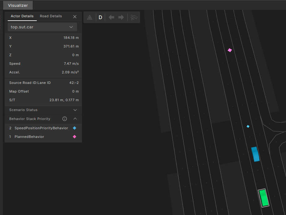
Select an actor in the Visualizer frame and click the Actor Details (i) icon in the top left corner. The Actor Details display:
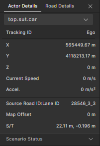
The X, Y, and Z coordinates, and the speed and acceleration display, as well as the following:
- Road ID: Lane ID: Represents the road/lane ID on which the actor is driving, from the original map representation (for example, from an OpenDrive map).
- Tracking ID: The original tracking ID assigned to the actor in the object list from the recorded data.
- Map Offset: The longitudinal offset of the Foretify map implementation (MSP) from the longitudinal position in the original map representation.
- S/T: Represents the longitudinal (S) and lateral (T) offset from the lane reference line, in Foretify map (MSP) coordinates.
- Dynamic Control: Displays the state of the vehicle actuators if the vehicle is driven dynamically. See View Dynamic Control.
- Foretellix SUT Model Control: Displays the state of the vehicle actuators if the Foretellix SUT Model driver (referred to as the Foretellix SUT Model) is integrated. See Foretellix SUT Model Control.
- Scenario Status: Traces the internal state of an actor. See View Scenario Status.
- Behavior Stack Priority: Traces the driver behavior state. See View Behavior Stack Priority.
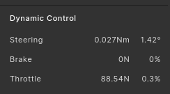
View Dynamic Control
In the Actor Details, you can view the state of the vehicle actuators (brake and throttle pedals, and the steering wheel) and the force or torque applied on them for vehicles that have "dynamic" physical_drive.
View Foretellix SUT Model Control
In the Actor Details, you can view the state of vehicle actuators (brake pedals, throttle pedals, and the steering wheel) if the Foretellix SUT Model driver is integrated. See the Foretellix Driver module for details.

View Scenario Status
In the Actor Details, you can view scenario status information that traces the internal state of an actor at a specific point in time.
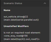
-
Name shows the current scenario that this actor is executing. Hovering above the scenario text displays a tooltip with the full scenario information.
If the current move is part of an implicit phase, where the driving phase is not defined explicitly, the text will be either:
-
"Waiting for <>" which means Foretify is waiting for start conditions of a specific scenario to be satisfied.
-
"After <>" which means Foretify finished the last scenario for this actor and is just driving the actor until the run ends.
-
-
Unsatisfied Modifiers show the modifiers (and hence constraints related to the modifiers) that are currently not met and prevent the actor from progressing to the next phase. Hovering over an unsatisfied modifier displays a tooltip with the full information which includes:
- Modifiers with "at: end" for the active scenario
- Modifiers with "at: start" (or "at: all") for the next scenario
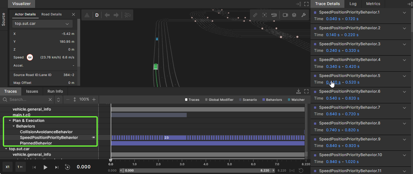
View Behavior Stack Priority
In the Actor Details, you can view the Behavior Stack Priority which traces the driver behavior state.
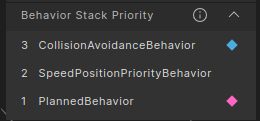
Foretify's driver component activates different behavior components based on drive conditions. Behaviors are sorted by priority. The highest priority has the highest index in the list. In the example above, this is the CollisionAvoidanceBehavior, which has an index of 3. The higher priority behaviors in the stack override the decisions of lower-priority behaviors. The applied behavior is marked in light blue and the planned behavior in purple. These colors correspond to the driver behaviors view tool on the map.
See Driver behaviors for descriptions of the driver behaviors.
Work with the View Tools
The View Tools change how objects are displayed in Visualizer. To access the View Tools, in the Visualizer, click the View Tools ![]() icon in the top right corner and select the tools you want to use.
icon in the top right corner and select the tools you want to use.
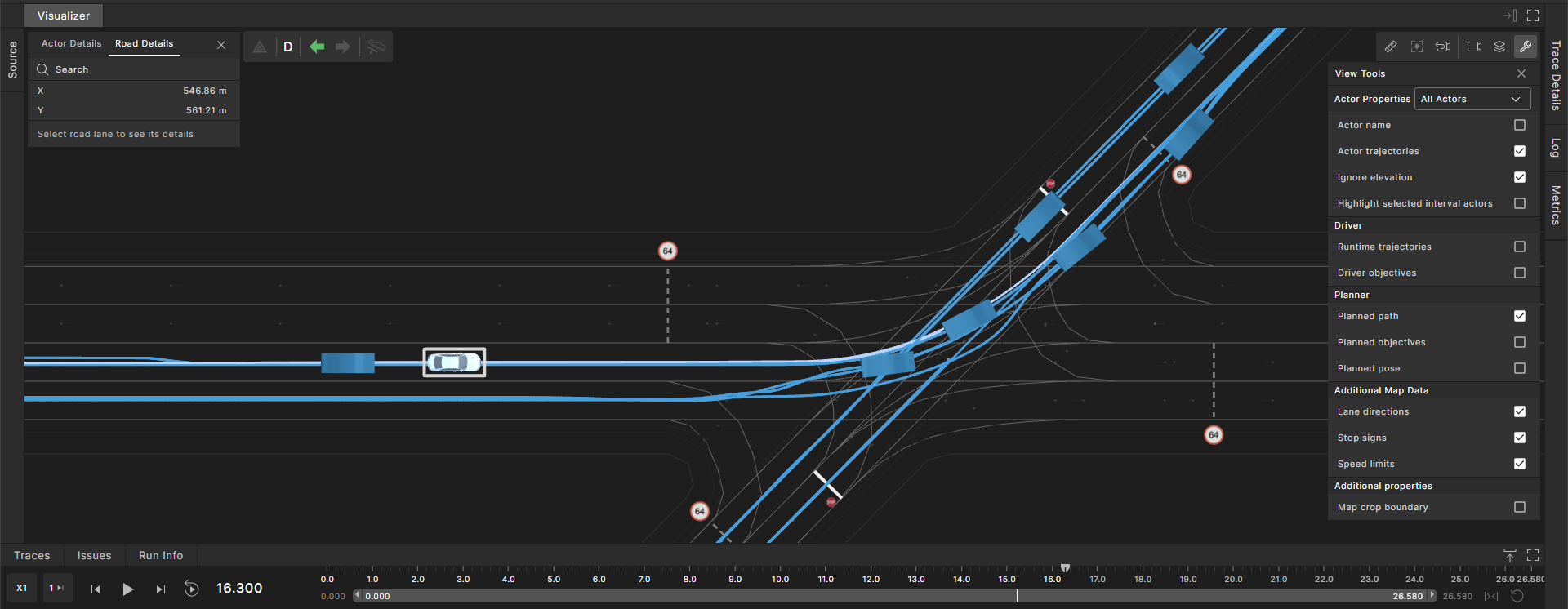
By default, View Tools are displayed for the currently selected actor only. In the example below, the sedan is selected, so only its Planned path is displayed:
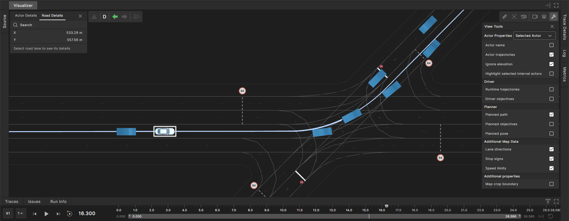
From the Actor Properties dropdown menu, change Selected Actor to All Actors to display all actor-related view tools. For example, when All Actors selected, the planned paths for all actors are displayed simultaneously:
| Tool | Description |
|---|---|
| Lane direction | Displays arrows that represent the direction of each lane. |
| Traffic lights | Displays traffic lights and their corresponding dynamic, colored traffic light-state lines, if present in the current run. |
| Stop signs | Displays stop signs and their corresponding stop lines, if present in the current run. |
| Yield signs | Displays yield signs, if present in the current run. |
| Speed limit | Displays speed limit signs, if present in the current run. |
| Collision avoidance | Displays a Time to Collision (TTC) vector between the actor and the collision target. |
| Runtime trajectories | Displays the trajectory of the selected actor. See View runtime trajectories for an example. |
| Planned path | Displays the path generated by the test generation engine that the selected actor follows. See View paths and poses for an example. |
| Planned objectives | Displays points that represent the target driving points through which non-ego actors should attempt to pass. See View planned objectives for an example. |
| Planned pose | Displays the position planned by the test generation engine for the selected actor. See View paths and poses for an example. |
| Driver objectives | Displays the driving objectives generated for the selected actors. See View driver objectives for an example. |
| Projected pose | Displays the projected position of the selected actors when track: projected is used in a modifier. See View paths and poses for an example. See also how to use the track parameter. |
| Actor Name | Displays the selected actor's name above its depiction. See View actor names for an example. |
| Actor trajectories | Displays the actual trajectories the actors followed during the simulation or real-world recording. See View Actor Trajectories for an example. |
View Map information in Visualizer
When running a test with Execute a run flow, map information appears inside the Visualizer. Map information is also available when loading previous runs and when loading runs in Foretify Manager.
Note
This works only for runs created with version 24.11 or newer.
Cropped maps:
When loading a previous run that was executed with map cropping enabled, several indicators will appear: - The cropping boundaries will be displayed on the map as a gray rectangle. - To hide this visual indicator, you can uncheck Map crop boundary in the View Tools menu.

- A cropped label will be added next to the map name.
Any road that is partially or fully within the region will be included.
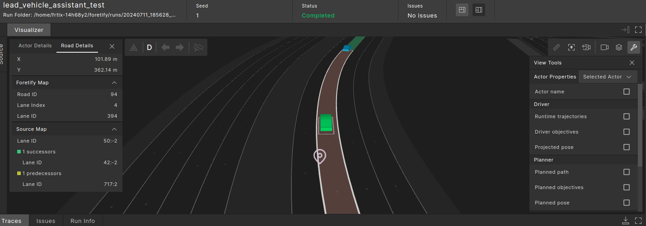
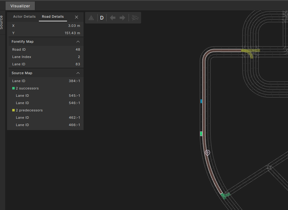
To see the attributes of a selected road element:
- Click the Road Details tab at the top-left corner of the Visualizer.
-
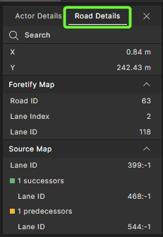
View detailed information about road elements in Road details:
- X and Y display the road coordinates on the map.
- Foretify Map shows the Road ID, Lane ID, and Lane Index as they are represented internally in Foretify's MSP format. See Map format requirements and MSP implementation guide for more details on the MSP format
- Source Map shows the road's Lane ID as well as the Lane IDs for the road's successor and predecessor roads as they are represented in the source map's format.
When clicking on a lane, the predecessor and successor lanes are highlighted on the map. Hovering over a lane shows the map ID of the lane as it is represented in the source map’s format.
To focus the camera on a selected road:
- Click the Focus camera on selected road icon
 or use the Shift+R shortcut to focus the camera on the selected road.

To find a road element of a selected type:
- Click the Route Elements (stack) icon
 at the top-right corner of the Visualizer, to the left of the view tools icon.
 - In the Route Elements list, select the route element type you want to focus on. Elements of the selected type are highlighted in various colors.
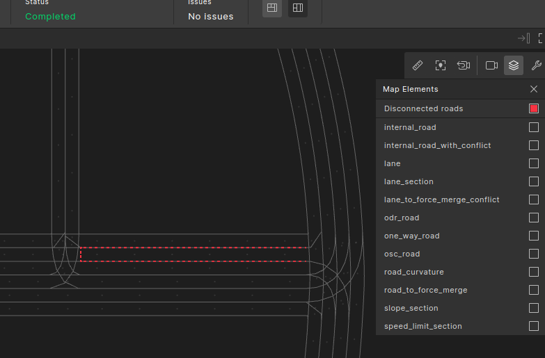
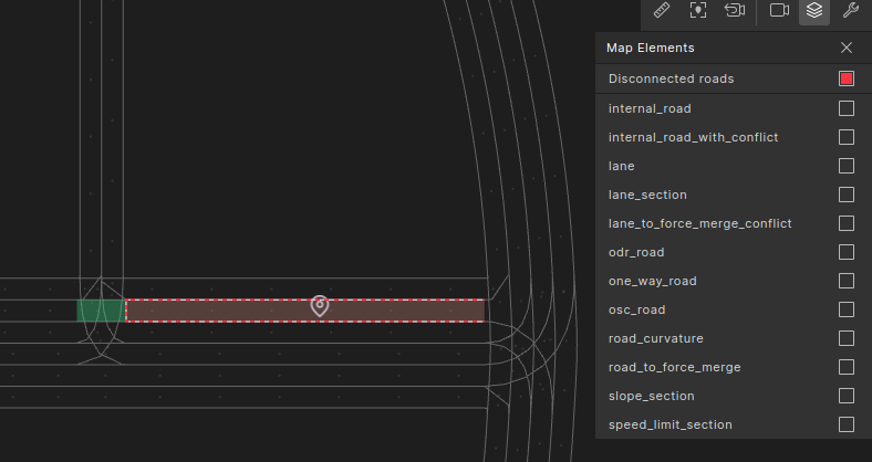
To display disconnected roads:
- Click the Route Elements (stack) icon at the top-right corner of the Visualizer, to the left of the view tools icon.
- Select Disconnected roads to show lanes that do not have successor or predecessor lanes.
- In many cases, when such disconnected roads appear, they indicate anomalies in how the map was constructed and are a common source of test failures.
- Click on the disconnected road to reveal its missing connectivity and help debug issues.
To search for a specific lane by ID using the road details search option:
Note
This works only for runs created with version 24.11 or newer.
-
Go to the Road Details tab.
-
Click Search.

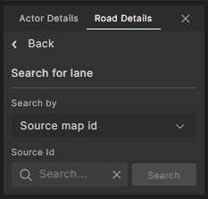
Result: The search section is displayed within the Road Details tab.
-
Select the required Road type:
-
Source map ID: The lane ID in the original map terminology.
-
Road MSP ID: The road ID in the MSP terminology. Note: When searching by road MSP ID, the first lane (index = 1) of that road will be selected.
-
Lane MSP ID: The lane ID in the MSP terminology.
-
-
Enter the respective ID in the input box.
-
Click the Search button.
Result:
-
If the lane is found, it will be selected on the map. The map may be zoomed or rotated to display the entire lane.
-
If the lane is not found, an error message will be shown.
-
View actor trajectories
To view actor trajectories:
-
In the Visualizer, click the View Tools
icon. -
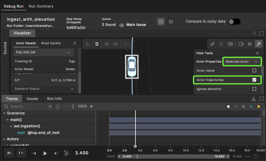
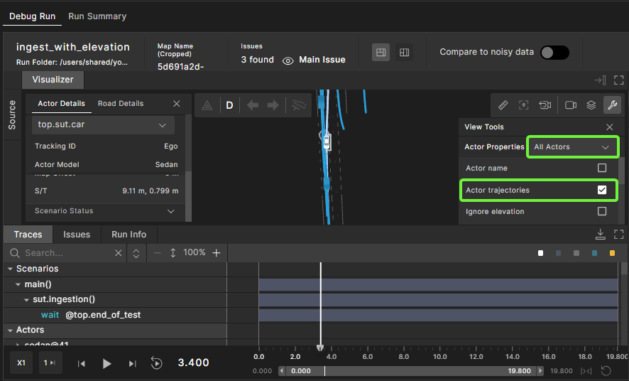
In the Actor Properties dropdown menu, select Selected Actor to view a single trajectory, or All Actors to view all trajectories.
-
Select Actor trajectories.
If you select a single actor, that actor’s trajectory is displayed:
If you select all actors, the trajectories of all actors are displayed:
View runtime trajectories
To view runtime trajectories, in the Visualizer click the View Tools ![]() icon, and select Runtime trajectories.
icon, and select Runtime trajectories.
As the Foretellix Human Driver model drives either the SUT (for example, in ADAS testing while no ADAS function is active) or an NPC, it creates intermediate short-term trajectories on which it drives. (For a discussion of driver models, see the Forellix Driver module.)
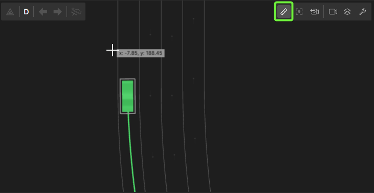
The following image shows a runtime trajectory (in magenta):
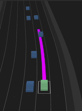
The color of the trajectory line relates to the speed of the actor. Following is the color gradient, where the lower end (red) correlates to 0 m/s and the high end (green) correlates to 60 m/s.

Any speed below 0 displays the same color as 0. Any speed over 60 displays the same color as 60. Any speed within the range displays the color according to its relative position in the gradient.
View paths and poses
To view paths and poses, select any of the following from the View Tools: Planned path, Planned pose, and Projected pose.
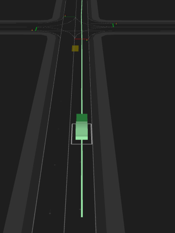
In the following image, the planned path, the path generated by the test generation engine that the actor will follow, is the light green line. The planned pose, the position planned by the test generation engine for the selected actor, is the dark green box. The projected pose, the projected position of the actor when track: projected is used in a modifier, is the brown box.
View planned objectives
Planned objectives are points that represent the target driving points through which non-ego actors should attempt to pass.
To view planned objectives for the selected actor, select Planned objectives from the View Tools. (Access the View Tools by clicking the wrench icon ![]() on the top right of Visualizer.) The selected actor is highlighted. Change Selected Actor to All Actors to display all of the actors' planned objectives.
on the top right of Visualizer.) The selected actor is highlighted. Change Selected Actor to All Actors to display all of the actors' planned objectives.
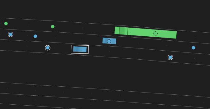
The planned objectives are shown as circles on the map and the color of the circles match the color of the actor. The planned objectives for the selected actor display with a white border.
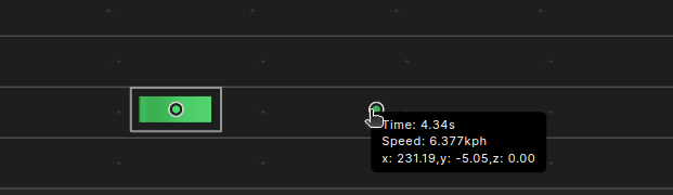
Hovering over a planned objective displays a tooltip with that objective’s position, time and speed.
View driver objectives
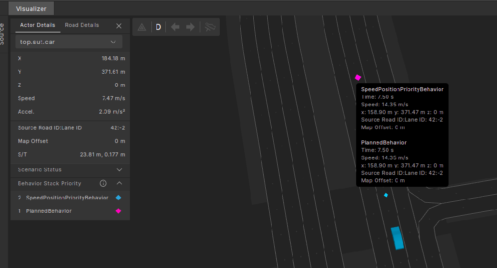
As the Foretellix Human Driver model drives either the SUT (for example, in ADAS testing while no ADAS function is active) or an NPC, it creates intermediate targets to which it drives. These targets are called driver objectives.
To view driver objectives for the selected actor, select Driver objectives from the View Tools. (Access the View Tools by clicking the wrench icon ![]() on the top right of Visualizer.)
on the top right of Visualizer.)
When Driver objectives is selected, each actor shows two objectives as diamonds, the original objective and the active objective that is adapted by active driver behaviors.
The original driver objective based on the Planner instructions is purple and the active driver objective is light blue. The active driver objective might be different from the planned one as a result of an intervention of higher priority behaviors. It is common for both driver objectives to be in the same place. In this case, the active driver objective is drawn on top of and slightly smaller than the original so you can see the original driver objective as a purple border around the light green active driver objective.
The behavior stack priority section in the actor details indicates which behaviors are marked on the Visualizer by attaching a similarly colored diamond shape to the annotated behaviors on the map.
Hover over any driver objective to get a quick glance at the vehicle’s objective behavior details (time, speed, position, source road/lane ID, and map offset).
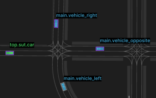
View actor names
To view the actor names on top of the actors, select Actor Name from the View Tools. (Access the View Tools by clicking the wrench icon ![]() on the top right of Visualizer.)
on the top right of Visualizer.)
Highlight selected interval actors
To see the participating actors in a specific interval, click the View Tools icon ![]() and select Highlight selected interval actors.
and select Highlight selected interval actors.
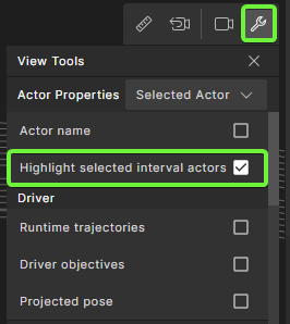
When this mode is enabled, clicking an interval in the Traces view highlights all actors participating in that interval in the following ways:
- For evaluation match and anomaly intervals, all matched actors are highlighted.
- For generative intervals (scenarios and watchers), the actor that emits the interval is highlighted.
Compare noisy and denoised data
This feature helps you compare noisy and denoised data in a run using the Visualizer.
To compare:
-
Toggle on Compare to noisy data.
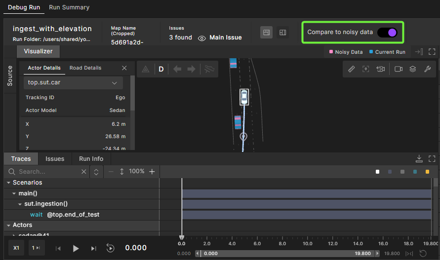
-
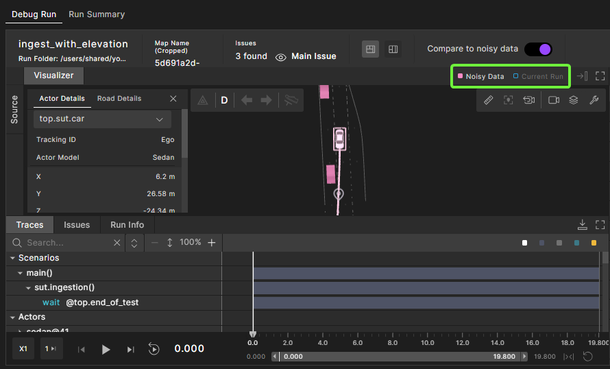
Select Noisy Data and deselect Current Run to view the noisy data, or vice versa to view denoised data.
The following image shows the noisy data in the run:
Measure distances in Visualizer
Use the Measure Distance tool to take measurements in the Visualizer window.
Note
You can only take measurements in Visualizer's orthogonal view. To do so, turn off Perspective view.
To measure distances:
-
If Visualizer is in Perspective view, select the Camera Settings icon
on the top right of Visualizer and turn off the Perspective view option. 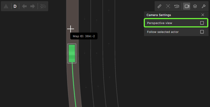
-
Select the Measure Distance tool icon
 .
.
-
Point and click in Visualizer to set the starting point of your measurement, then move the cursor and click to set the end point of your measurement.
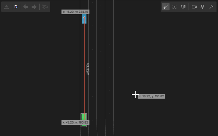
The measurement displays next to the line that connects the starting point and end point.
-
To hide the measurement, toggle off the Measure Distance tool icon
.
View vehicle indicators
If your scenario uses vehicle indicators, you can view a vehicle's indicators in Visualizer by selecting the vehicle.
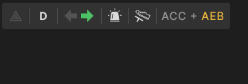
The vehicle indicators panel includes the following indicators:
| Indicator | Name | Possible values |
|---|---|---|
 |
hazard light | Displays in red for On and gray for Off. |
 |
current gear | Displays D for drive and R for reverse. |
 |
turn signal | Displays left or right arrows in green for On and gray for Off. |
 |
emergency lights | Displays in white for On and gray for Off. |
 |
brake signal | Displays in white for On and gray for Off. |
 |
ADAS modes | Lists the names of active and/or engaged ADAS modes separated with a + sign. Displays in gray for Active and yellow for Engaged. In the example shown, ACC is engaged and AEB is active. |
Debugging in Traces view
All traces can be viewed under the Traces view. The Traces view is aligned with the timeline, so you can easily compare different traces.
Value and interval traces
Traces are represented as these distinct types:
-
Values: Represent a single value as it changes over time. Values are displayed as waveform graphs.
- A value trace is created using the OSC2 trace statement.
- Value traces have a name, value and unit.
- Value traces are associated with a specific actor.
-
Intervals: Represent a collection of values collected over a period of time.
- Intervals have a name, start time, end time and type.
- Intervals are associated with a specific actor.
- OSC2 constructs that create intervals are scenarios and watchers and checkers.
With value and interval traces consolidated in the Traces tab, you can answer questions like "When this scenario ended, what was the distance between the SUT and the NPC?" or "When this watcher was fired, what was the SUT speed?"
Traces tree organization
The Traces tree is organized by:

Scenarios
The Scenarios tree displays the scenario execution as intervals.
Foretify provides intervals as a way to represent, store, and visualize abstract data over a time span within a Foretify simulation run. Intervals are represented as interval traces in the Traces view. Intervals allow you to analyze your run at a higher level of abstraction. Intervals can appear in both the Scenarios and Actors subtrees.
Foretify generates scenario intervals that show the execution of each scenario in a test run, allowing you to visualize the execution sequence. An interval is data that captures some behavior over a period of time. It has a title and a set of attributes. Foretify also generates coverage intervals that contain the samples of each coverage point in a test run. Coverage intervals can be accessed using the API. See Coverage Interval for details.
You can use interval data to determine whether a scenario was executed or whether a metric was sampled and when. An interval has a start time and an end time and hence a duration, which can be 0 (start time = end time).
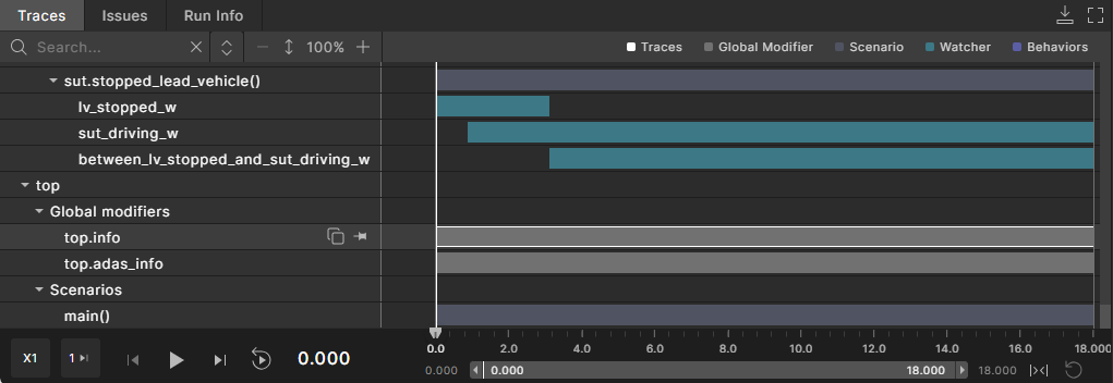
To generate the visualization, Foretify records the start and end times of every built-in scenario (for example, serial, parallel, and drive) and user-created scenarios in the test under top.main. The interval for a scenario is named after the scenario or the user-defined label, if provided. Intervals display any metrics collected during the interval execution as attributes.
Scenario names
Scenario names in the scenario tree are constructed as follows:
- Scenarios with special roles in the OSC language are displayed in blue. These special role constructs include: wait, call, parallel, serial, first_of, and emit.
- Scenarios with a user-defined label are displayed in yellow.
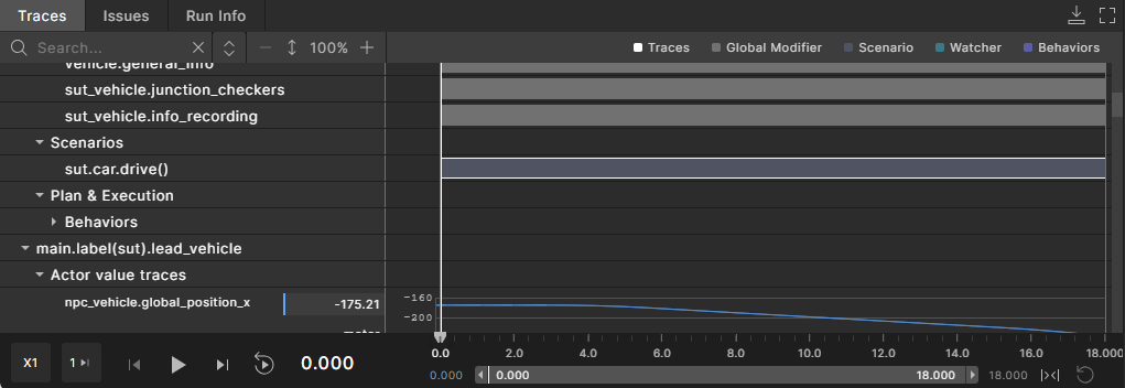
- Scenarios representing an invocation (which typically refers to the instantiation or execution of a scenario or modifier, such as
sut.car.drive()) are shown in white. The representation of invocations varies across different OSC scenario constructs:- serial, parallel, first_of: These constructs do not involve explicit invocation, so no invocation details are displayed.
- call: Displays the method path, for example:
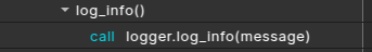
- wait: Displays the event expression associated with the wait condition, for example:

- emit: Displays the emitted event expression.
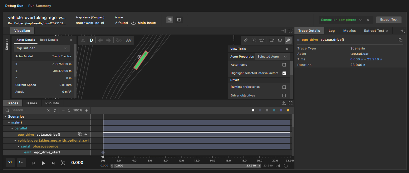
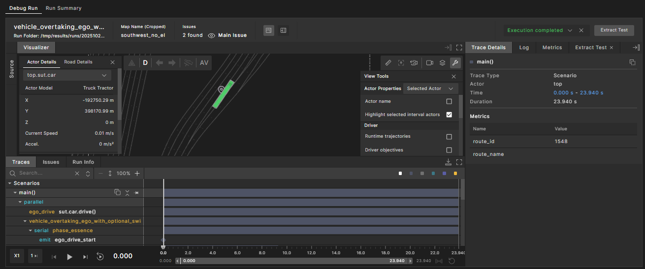
- non-special construct: Displays the scenario invocation path, for example
sut.car.drive()in the following image: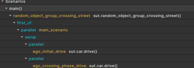
Hovering over a scenario name displays its full scenario path, as shown below. This full path can be used as an input for the Foretify print CLI command to further debug the scenario’s memory model in Foretify Developer. You can also click the copy ![]() button next to the scenario name to copy its full path to the clipboard.
button next to the scenario name to copy its full path to the clipboard.

Actors (visualized)
The Actors tree organizes value trace data and interval trace data organized in a tree structure:
-
Actor
-
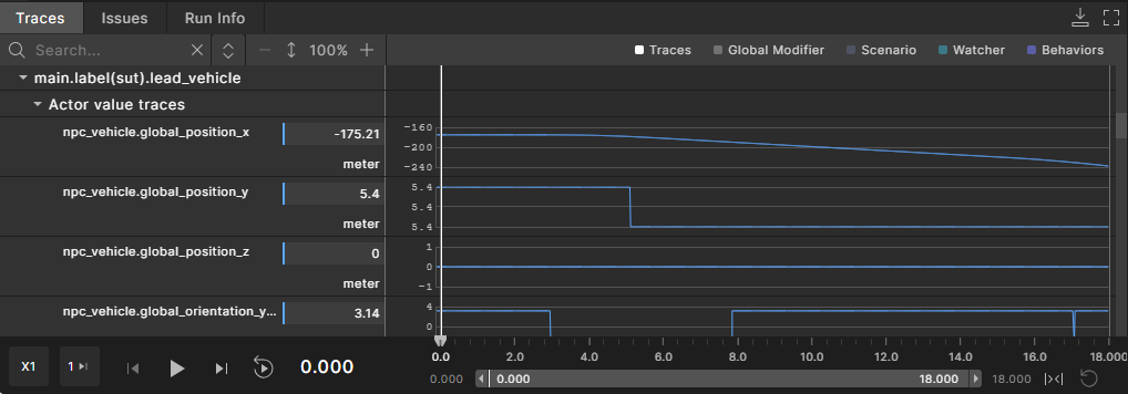
Actor value traces: Shows traces collected for the actor that are not scenario-specific.
- Traces and intervals can appear under any scenario.
- Value traces that are collected under the actor level appear under a special “Actor value traces” category.
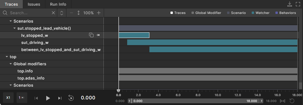
Interval traces that are emitted by watchers appear as intervals in the color teal:
-
Global modifiers: Shows a list of global modifiers defined for this run. Under each global modifier, it shows traces and intervals collected in that context.
-
Scenarios: Shows a list of scenarios defined for this run. Under each scenario, it shows traces and intervals collected in that context.
-
Plan & Execution: Shows internal debug data from Foretify’s planning and execution components, such as driver behavior intervals.
-
See Analyzing watcher and checker intervals in the debugger for more details.
Match scenarios
Real-world scenarios detected by the Evaluation Pipeline are grouped under a dedicated section called ‘match scenarios’. The example is given below in the screenshot.
Actors (non visualized)
Some actors displayed in the Traces view may not appear in the Visualizer. For example, actors that represent internal entities in Foretify ('top'). Such actors are grouped under the ‘Actors (Others)’ section. The example is given below in the screenshot.
Work with value and interval traces
To view value and interval trace details:
-
In the Debug Run tab, click the Traces view under Visualizer.
-
Navigate to the trace you're interested in by selecting the arrow to the left of the Scenarios or Actors categories to see their children.
-
Select a value or interval trace in the Traces view.
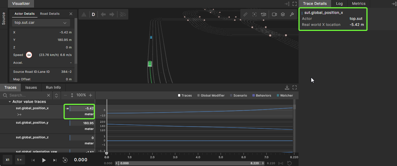
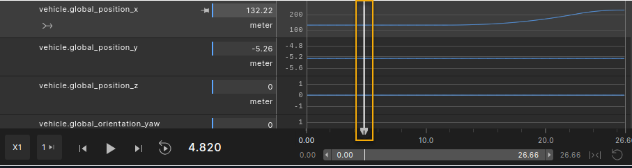
Value and interval traces are shown in a timeline that corresponds to other time-based views such as Visualizer.
-
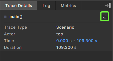
View the details of the interval or value in the Trace Details tab on the right.
The Trace Details tab displays:
- The trace name
- The basic details for the trace. For intervals, the data includes the start time, end time, duration, and metrics collected during the interval. Metrics can be collected per interval using the cover and record OSC2 statements.
For value traces, you can also see the current values as part of the Traces view, to the left of the waveform graph. Clicking on a value trace at a specific point on the timeline displays that value’s trace details under the Trace Details tab as well.
Different trace types appear in different colors. The top right of the Traces view contains a legend for these colors.
Click on a trace type in the legend to hide or show all traces of that type. In the following example, only watchers and checkers (marked with severity error and warning) are selected in the legend area.

Intervals of length 0 appear in a diamond shape.
To collapse and expand traces:
By default, the Traces view displays all tree nodes expanded.
-
To collapse all tree nodes, click the Collapse Tree icon
 at the top of the Traces view.
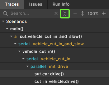
Note that if the tree is fully expanded, this button will be in collapse mode. If not all of the tree nodes are fully expanded, the button will be in expand mode.
-
To expand all tree modes, click the Expand Tree icon
 in the same location.
 -
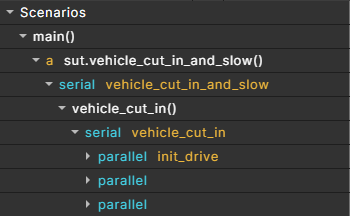
To collapse an expanded subtree, hover over the expanded tree node and click the Collapse icon
that appears. The entire subtree is collapsed. The collapse is granular, meaning that when collapsing a parent node, its children keep their expansion state and do not collapse with the parent. -
To expand a collapsed subtree, hover over the collapsed tree node and click the Expand icon
that appears. The entire subtree is expanded. The expansion is granular, meaning that when expanding a parent node, its children keep their expansion state and do not expand with the parent.
To search for traces:
Use the search bar to narrow down the Traces view for a specific trace name.
Searching causes a full expansion of the nodes matching the search criteria.
Clearing the search bar returns the tree to the exact state it showed before, meaning the pre-search expand and collapse states are shown.
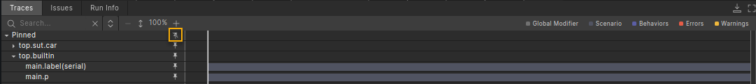
To pin a trace to the top of the Traces frame:
Hover over a trace and click the Pin icon that appears next to the element name.

You can pin any type of element in the Traces view to the pinned area:
- A specific trace element (a value trace or interval trace)
- The container subtree of a value trace or interval trace
When pinning any type of element, the full path to the element is pinned, as well:
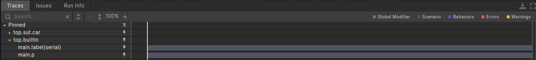
When you pin an element, the pin icon changes from a horizontal pin to a vertical pin. Click the vertical pin to unpin the element. Click the Unpin All icon to unpin all of the pinned elements:
Pinned traces remain persistent throughout the session. They persist in the pinned area after reloading the test, rerunning with different seeds, or when loading other tests. If the newly loaded test does not have value or interval traces recorded, it is not shown in the pinned area.
To increase the size of value traces:
-
To increase the size of all value traces, click the + icon at the top of the Traces view.
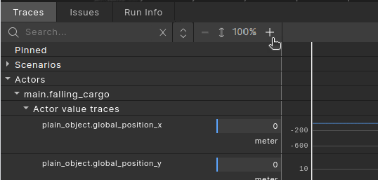
-
To decrease the size of value traces, click the - icon at the top of the Traces view.
To merge multiple value traces into a single graph:
-
Hover over a value trace (parameter name) and click the Merge icon that appears beneath the parameter name.
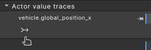
-
Select the parameters you want to merge from the dropdown list.
You can merge only parameters that have the same unit.
To add custom value traces to a test:
-
In your favorite editor, edit the test file to extend the scenario to add one or more trace() modifiers.
OSC2 code: trace()extend top.main: do c: cut_in_and_slow() with: trace(car1_speed, exp: car1.state.speed, unit: kph) trace(sut_speed, exp: sut.car.state.speed, unit: kph) trace(speed_diff, exp: car1.state.speed - sut.car.state.speed, unit: kph) trace(cutin_side, exp: side)For a complete description of the trace() modifier, see trace in OSC2 Language.
-
In the Load tab, reload the test file into Foretify Developer.
-
When the Prepare Test tab opens, click Terminal in the top right corner.
-
Execute one or more trace commands at the command line prompt in the Terminal.
Foretify command: traceForetify> trace sut.cut_in_and_slow.* Timeline: 1. top.main.car1_speed 2. top.main.sut_speed 3. top.main.speed_diff 4. top.main.cutin_sideFor a complete description of the trace command, see trace.
-
In the Prepare Test tab, execute the run.
Export interval as a URL
If the debugger is accessed from Foretify Manager and the server connection uses HTTPS (rather than HTTP), an icon appears next to the interval name to copy the interval as a URL.
Clicking the icon copies the URL to the clipboard. The copied URL includes the run link combined with the interval, making it easy to share a specific interval with other users.
After a successful copy, a brief Copied notification is displayed. When the copied URL is pasted into another browser tab, the Single Run Debugger opens the same run and focuses on the copied interval.
Work with driver behaviors intervals
You can debug Foretify driver behaviors using the Traces tab.
Foretify's driver component activates different behavior components based on drive conditions. An interval is created for the duration of a driver behavior activity. Under each actor, the “Plan & Execution” section contains the “Behaviors” section.
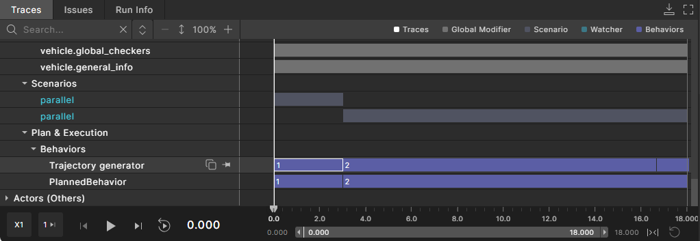
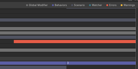
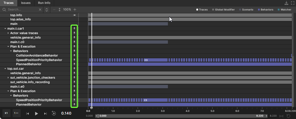
Behaviors intervals are sorted by priority, and displayed from the highest priority at the top to the lowest priority at the bottom, as shown in the following image:
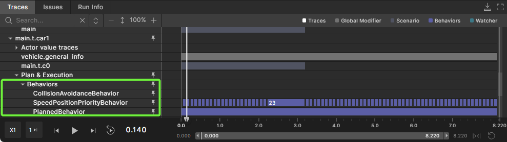
In this example, for the car, the highest priority is CollisionAvoidanceBehavior, then SpeedPositionPriorityBehavior and the lowest priority is PlannedBehavior. The higher priority behaviors in the stack override the decisions of lower-priority behaviors. See Foretellix Driver for descriptions of the driver behaviors.
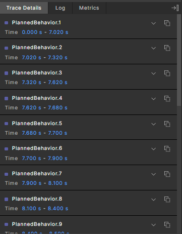
Each driver behavior is expressed as an interval type. When the behavior is active, an interval instance is emitted. The interval shows the period for which the behavior was active. The number displayed on the intervals is a running number, from the first to the last interval.
Clicking on a behavior interval instance shows the following information in the Trace Details pane:
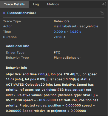
| Field | Description |
|---|---|
| Trace Type | Set to "Behaviors". |
| Actor | Displays the actor for which the behavior is active. |
| Time | Displays the time during which the behavior was active. |
| Duration | Displays the duration of the active behavior. |
| Additional info | Driver Type: Can be "FTX" or "HLM". Learn more about the Foretellix Driver. |
| Behavior info | Displays a verbose message with details on the behavior's operation. |
As with any other interval, you can analyze multiple behavior details by selecting the entire interval line.
You can pin behavior intervals to the pinning area for better comparison of the behaviors of different actors.
Driver behaviors
The following table includes the types of driver behaviors that display in the Behaviors section of the Traces tab and the Actor Details Behavior Stack Priority list.
| Behavior | Description |
|---|---|
| ADASOverrideBehavior | Specifies how the ftx_driver should act when it is in control and an ADAS function interrupt occurs. See ADAS override behavior. |
| BypassBehavior | Detects stationary obstacles that are blocking the way of the actor to reach its input objective. See bypass_behavior. |
| CollisionAvoidanceBehavior | Uses the scenery information coming from the perception layer and the scenery_processing_utility library to find the most dangerous objects in the actor's proximity and performs collision avoidance maneuvers based on the predicted interaction with them. See collision_avoidance_behavior (CollisionAvoidanceBehavior). |
| CustomerBehavior | Uses customer-specific logic and allows special adaptations for the customer's needs. |
| EndingLaneBehavior | Handles lane merges when the next lane is occupied. See ending_lane_behavior. |
| EndOfRoadBehavior | Handles stopping the vehicle either if the lane ends or the road reaches the end of the map. See end_of_road_behavior. |
| JunctionBehavior | Moves a vehicle through a junction, observing the rules of the junction. See Junction behavior. |
| JunctionEntryLaneBehavior | Handles situations in which the vehicle enters junctions on incorrect lanes (with regard to the planned path). |
| KeepOnDrivingBehavior | Handles cases where the planned behavior is no longer valid. (The vehicle passed the position, but the next phase of the scenario was not initiated.) |
| PlannedBehavior | Interprets the planned goal of the move_op and produces the proper objective. PlannedBehavior is the first behavior that is called (in the ftx_driver), and the objective it produces serves as the input objective for all other behaviors. |
| PostCollisionBehavior | Handles the motion of a vehicle during and after a collision. See post_collision_behavior. |
| RandomCruiseBehavior | Drives vehicles for which no plan is generated; such vehicles are mostly used in car_groups. |
| ShapeBehavior | Instructs the driver to execute a predefined trajectory. See Shape behavior. |
| ShiftBehavior | Allows manipulation of the input objective from the OSC2 scenario level. The manipulation is performed by applying a shift to the input objective or by setting a new absolute value. See shift_behavior. |
| SpeedAdaptationBehavior | Handles the adaptation of the vehicle's speed to the road curvature. See Speed adaptation behavior. |
| SpeedPositionPriorityBehavior | Ensures that actors will follow the plan in the best way possible according to the scenario writer’s priorities. |
| StayOnRoadBehavior | Handles adjustments of the vehicle's lateral position. See stay_on_road_behavior. |
Work with match intervals
When debugging a run, the Scenarios tree shows match scenarios. These are scenarios that were detected within a real world recording processed by Evaluation scenarios.

Each match scenario has an interval representing the scenario detected by the Evaluation Pipeline. Clicking on the interval shows the match scenario's basic details, the actors participating in the scenario, and any metrics that were recorded for that scenario in the Trace Details panel.
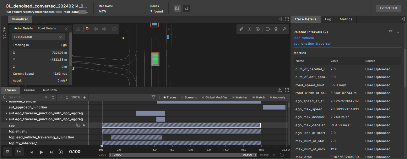
Match intervals can be grouped during the matching process into new intervals. When such group intervals are shown in the single-run debugger, the following tools are available for viewing the group interval content:
- An additional widget, Related intervals, is displayed with the list of intervals related to the group interval.
- In the Traces view, click the group interval to see the related intervals and their children.
- To navigate to a related interval, click on it.
Note that per actor, the following information is available:
-
Name: The actor name as defined in the OSC match scenario.
-
Actor ID: An ID given by Foretify.
-
Tracking ID: The original tracking ID assigned to the actor in the object list from the recorded data.
Visualizing match scenarios
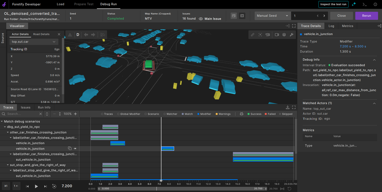
The Match Scenario Debugger UI allows evaluation scenario writers to visually inspect why an OSC match scenario did or did not match during an evaluation matcher run.
It simplifies traditional, code-heavy debugging by displaying the matcher's internal evaluation tree—scenarios, phases, actions, and modifiers—as color-coded, interactive timelines.
Benefit: Faster root cause analysis of false positives (unexpected matches) and false negatives (missing matches), saving time and improving accuracy.
- Visualizer timeline: Displays the same run as usual, with additional match debug intervals based on the debug flags provided.
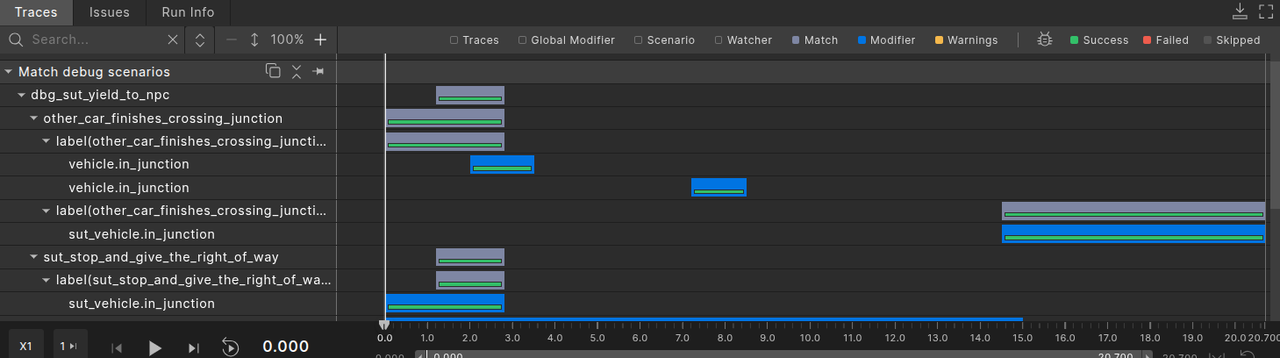
- Interval layers (including modifiers): Available only in debug mode and highlighted in blue for easy identification.
- Evaluation status legend: Color-coded to indicate status: Success is green, Failed is red, and Skipped is gray.
- Trace details: Provides key information, including start and end timestamps, evaluation state, OSC path, and invocation parameters.
To include debug information during the run, add the following two flags in the matcher run command:
--debug_actor <actor_recording_id>
Specify the actor ID. A substring of the ID is allowed, but it must be unique.

--debug_scenario <scenario_instance_name>
Specify the scenario instance name. The match must be exact.
-
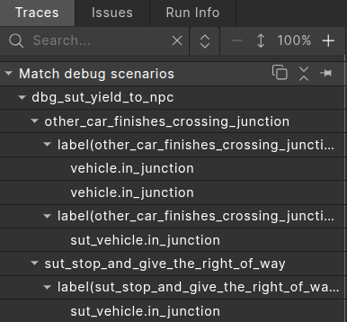
In the Traces view, expand Match debug scenarios tree.
-
Ensure that the Modifiers filter (shown in the blue legend) is enabled to view all modifiers and their debug status.
-
Use the Success, Failed, or Skipped filters in the top-right corner to display only modifiers with the selected status.
-
Click a modifier to view detailed information in the rightmost Trace Details panel. This includes time range, duration, debug data, matched actors, and relevant metrics.
User uploaded intervals
You can add intervals to an existing run using the Foretify Manager Python SDK. This allows you to apply custom post-processing logic and view the results directly in the single-run debugger as well as other Foretify Manager tools, such as triage and coverage analysis.
To create custom intervals using Python SDK, see CreateInterval API’s.
User-uploaded intervals can be added anywhere in the existing traces tree and will appear based on their parent scenario and actor.
User-uploaded intervals are shown in the traces view with a different visualization pattern, this distinguishes them from Foretify-generated intervals. The screenshot for the user-uploaded intervals (for car1_stop_and_give_the_right_of_way) is given below.

To filter user-uploaded intervals, click the filter icon, check User uploaded intervals, and uncheck Foretify intervals, as shown in the image below.
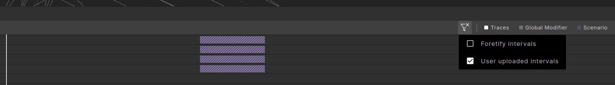
Similarly, you can filter Foretify intervals.
User-uploaded coverage groups and their metric items are displayed in the Trace Details > Metrics section with the source 'User Uploaded'.
Work with the timeline
The timeline is located at the bottom of the Foretify Developer window to the right of the playback icons.
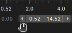
The timeline's zoom area consists of two parts. The numbers at the top indicate the zoom level in the Debugging in Traces view. The bottom grey bar displays the zoom range.
This section describes how to use the timeline. See also how to use the playback controls.
To zoom in using the timeline
-
To zoom in using the timeline, place the cursor on the start of the gray bar in the timeline and drag to the right or place the cursor on the end of the gray bar in the timeline and drag to the left.

You can drag the zoom range bar across the timeline, as well.
-
Click the reset icon on the right to reset the timeline.
To set the timeline to a particular time point:
-
Move the timeline cursor to that point in time.
Selecting and moving the time pointer is possible only inside the zoom range.
If the time pointer is outside of the time range, you can click the Play icon to move the pointer to the beginning of the zoom range bar and start playing. It will stop playing at the end of the zoom range.
If the time pointer is not inside the time range, a short white line appears on the time range to indicate where the time pointer is.
Tips
- To set the time pointer to the start of the time zoom range, use the shortcut: i
- To set the time pointer to the end of the time zoom range, use the shortcut: o
To see the value of a traced parameter at a particular point in time:
- Click on the trace at that point in time.
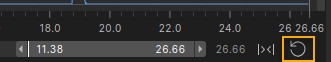
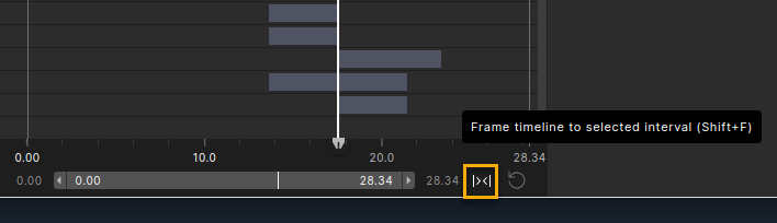
To frame the timeline to an interval:
-
In the Traces view, select the interval you want to frame the timeline.
-
Click the Frame timeline to selected interval icon to the right of the timeline.
-
To reset the timeline so that it no longer frames the interval, click the Reset Timeline icon to the right of the Frame timeline to selected interval icon.
Tips
- To set the time to the starting point of the framed area, use the shortcut: i.
- To set the time to the starting point of the timeline, use the shortcut: Control + i. This action also unframes the timeline if it is trimmed.
- If an interval row has multiple events (zero time or an interval with a duration) and an event is selected, you can jump to the previous (left) interval event by pressing 'j' or to the next (right) event by pressing 'k'.
View metrics
To see the metrics collected during the run:
- In the Debug Run tab, open the Metrics frame to the right of the Visualizer.
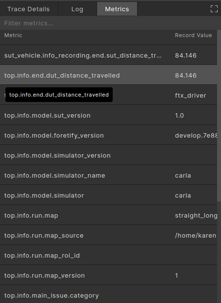
Notice that some of the metrics are displayed with buckets. Buckets are generated during Foretify runs based on coverage metrics defined in OSC2 code.
Note
Buckets are always open on the right end, so [1..2] includes 1 but not 2.
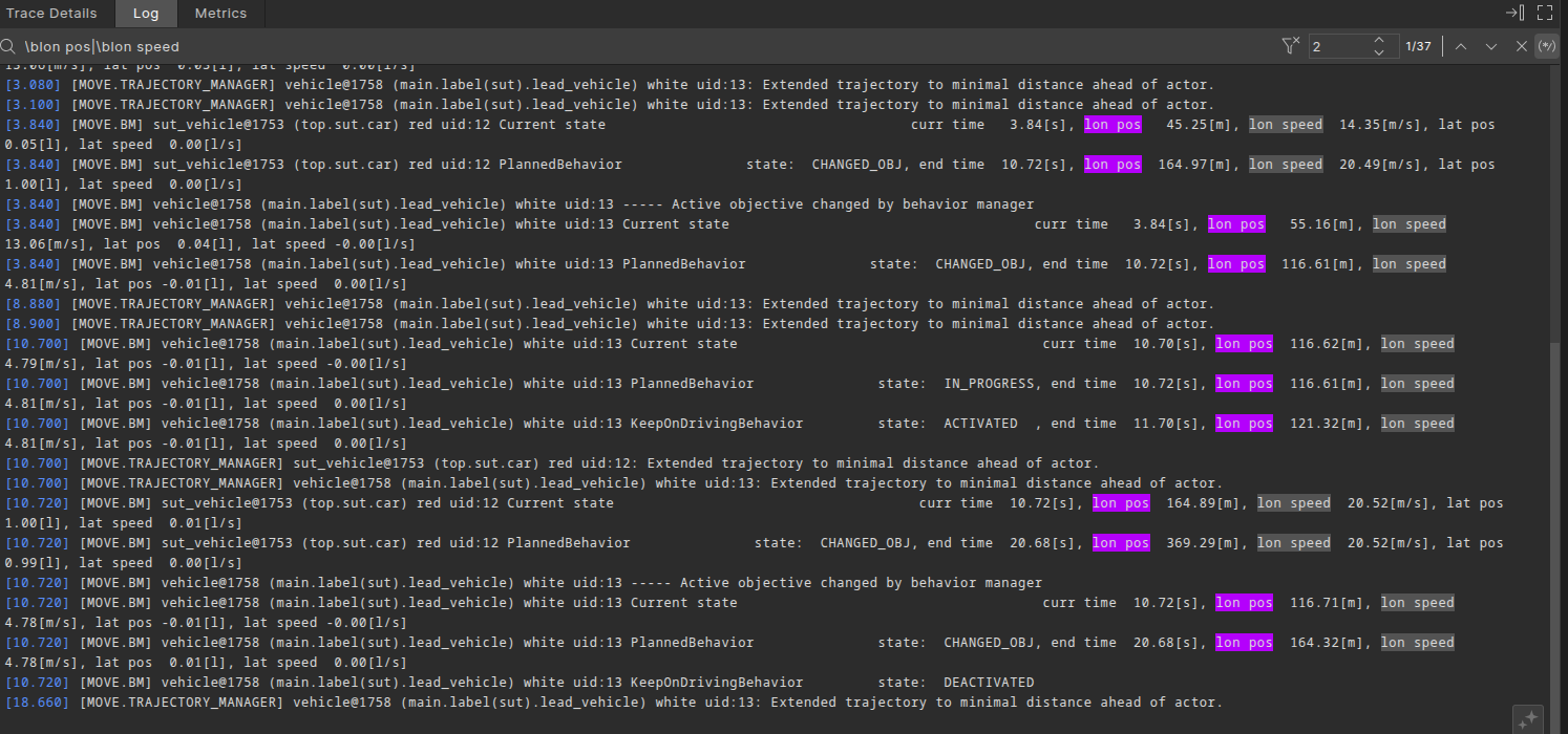
View Logs
To view the logs generated by Foretify during the run, click the Log pane.
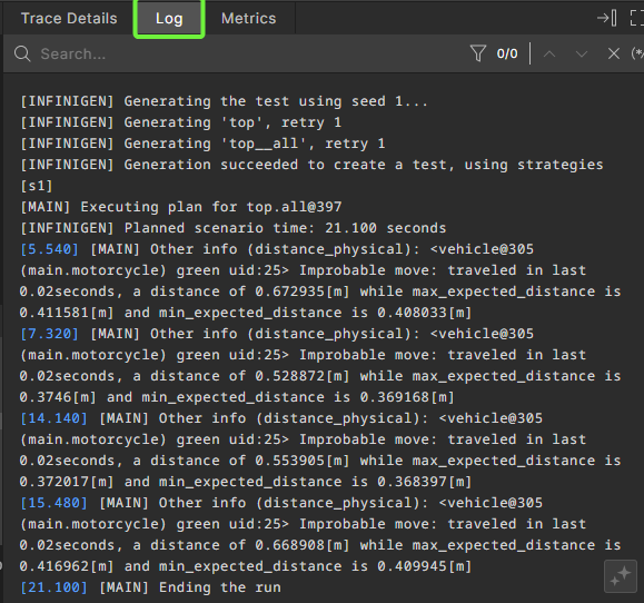
In Logs pane you can perform the following actions:
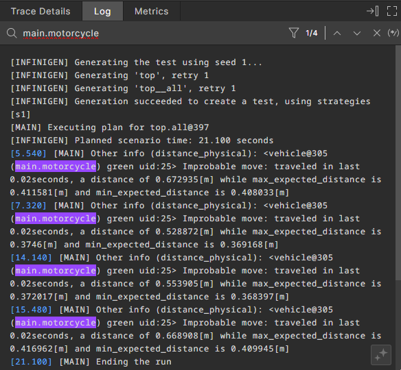
Searching logs
To search for specific information in the log, click the Search bar and enter the required text.

Result: The searched text is higlighted in the log.
Filtering logs
To view the log lines that exclusively matched the search text, click the Filter log by search text ![]() icon.
icon.
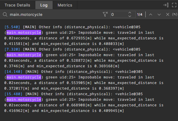
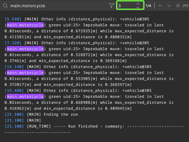
Use the Number of lines to expand filter ![]() icon to specify how many additional log lines should be displayed after each matched search result in filter mode.
icon to specify how many additional log lines should be displayed after each matched search result in filter mode.
Searching logs using regular expressions
To search for a log line using regular expressions, click the Search log by regex ![]() icon.
icon.
Result: The text found using the regular expression is highlighted, similar to a plain text search.
View run information
To view traceability information for a run, click the Run Info tab in the bottom pane.
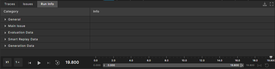
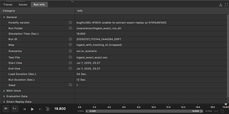
Note
The displayed sections may vary between runs based on their type and origin.
View video recordings in the Debugger
A run can have an associated video recording. The video can originate from:
-
A real-world video recording, for runs created by evaluation scenarios
If a video is available, the Visualizer contains a Video tab:
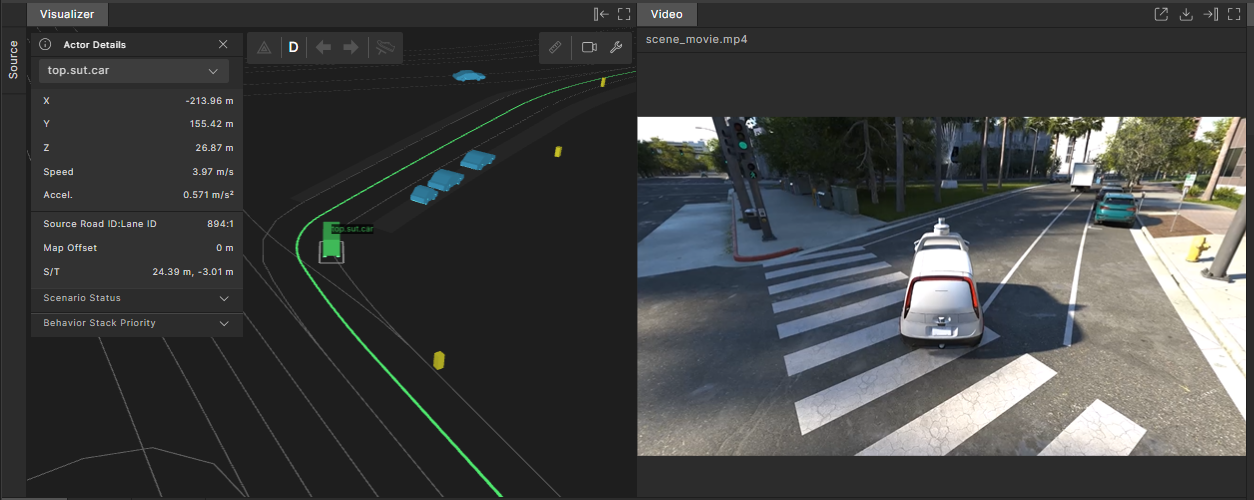
The Video tab is available in both vertical and horizontal layouts.
Note that zooming and tilting the camera angle in the Visualizer does not affect the video.
You can perform the following actions for video recordings:
-
Play the scenario to also play the video. The video is synchronized with the Visualizer view.
-
Click the Open Video in New Tab icon on the top right of the Video tab to open the video in a separate tab.
-
Click the Download Video Source icon on the top right to download the video to your local computer.
-
Click the Minimize icon on the top right to close the Video tab.
-
Click the Maximize icon on the top right to view the video in full screen mode within the Debugger.