Virtual routes elements
As part of the scenario random-generation process, Foretify enables constraint-based placement of imaginary roads on the map. The imaginary roads follow predefined patterns defined in XML format. These patterns may also have a “flexible” part that can bend along the road on which it is placed.
Examples of using imaginary patterns include modeling the following scenarios:
- A roadwork construction vehicle crossing the road
- Vehicles entering or exiting driveways
- Driving against the traffic direction
To use a pattern as an imaginary route it must be defined in an XML file and registered with a corresponding road_pattern_id enum value. Once registered, Foretify creates occurrences of crossing_path route element for that pattern. These crossing_path occurrences can then be placed on the map, within a scenario, using the modifiers top.path_along_drive or top.path_along_route.
Defining and registering patterns
XML pattern syntax
<roadPattern>
    <header fileVersion="1" >
        <patternParameters anchorOffset="<offset in meters>" />
    </header>

    <planView>
        <geometry hdg=<heading in radians> length=<length in meters> width=<width in meters>
           [specific geometry params]
        </geometry>
        ....
    </planView>
</roadPattern>
Parameters
-
anchorOffset: The position of the anchor point, which is calculated based on a specific position on a route. The rest of the pattern is placed relative to this anchor point. For more details, see the modifiers path_along_drive and path_along_route which are used to place the pattern. -
planView: This is one or more geometry entries. If multiple geometries are specified, then they are connected in the specified order, with the end point of one geometry serving as the starting point of the next. -
Geometry attributes:- hdg:
The heading of the start point of the geometry, expressed in radians. - length:
The length of the geometry. - width:
The width of the road around the centerline, defined by the geometry. The following geometry types are supported:- line:
The geometry is a straight line. - flexibleLine:
The geometry is a flexible line. When placed on a route, it follows the geometry of that route. A planView can have at most one flexibleLine geometry. - arc curvature="1/radius_in_meters:
The geometry is an arc with a radius of 1/curvature meters. The sign of the curvature indicates its direction: negative for clockwise, positive for counter-clockwise.
- line:
- hdg:
Note
If the pattern has a flexibleLine geometry then the anchorOffset must be on the flexibleLine.
Registering a pattern
The pattern defined in the XML file is associated with a road_pattern_id enum value by registering it in the following manner:
extend road_pattern_id: [my_pattern_id]
extend road_patterns_registry:
    def load() is also:
        register(my_pattern_id, "path/to/my_pattern.xml")
Predefined patterns
Three basic example patterns are provided with Foretify under $FTX/env/basic/road_patterns/ftlx_basic_patterns.osc
# Basic built-in patterns
# The list can be extended in subsequently loaded SDL files

extend road_pattern_id: [oncoming, traverse, s_curve]

extend road_patterns_registry:
    def load() is also:
        register(oncoming, "$FTX/env/basic/road_patterns/oncoming.xml")
        register(traverse, "$FTX/env/basic/road_patterns/traverse.xml")
        register(s_curve, "$FTX/env/basic/road_patterns/s_curve.xml")
crossing_path route element
The crossing_path route element represents an imaginary path that follows a pattern registered in the road_patterns_registry. The field kind:road_pattern_id can be used to constrain the pattern. The crossing_path is placed on the map either relative to a specific drive using the modifier top.path_along_drive, or relative to a route element using the modifier top.path_along_route.
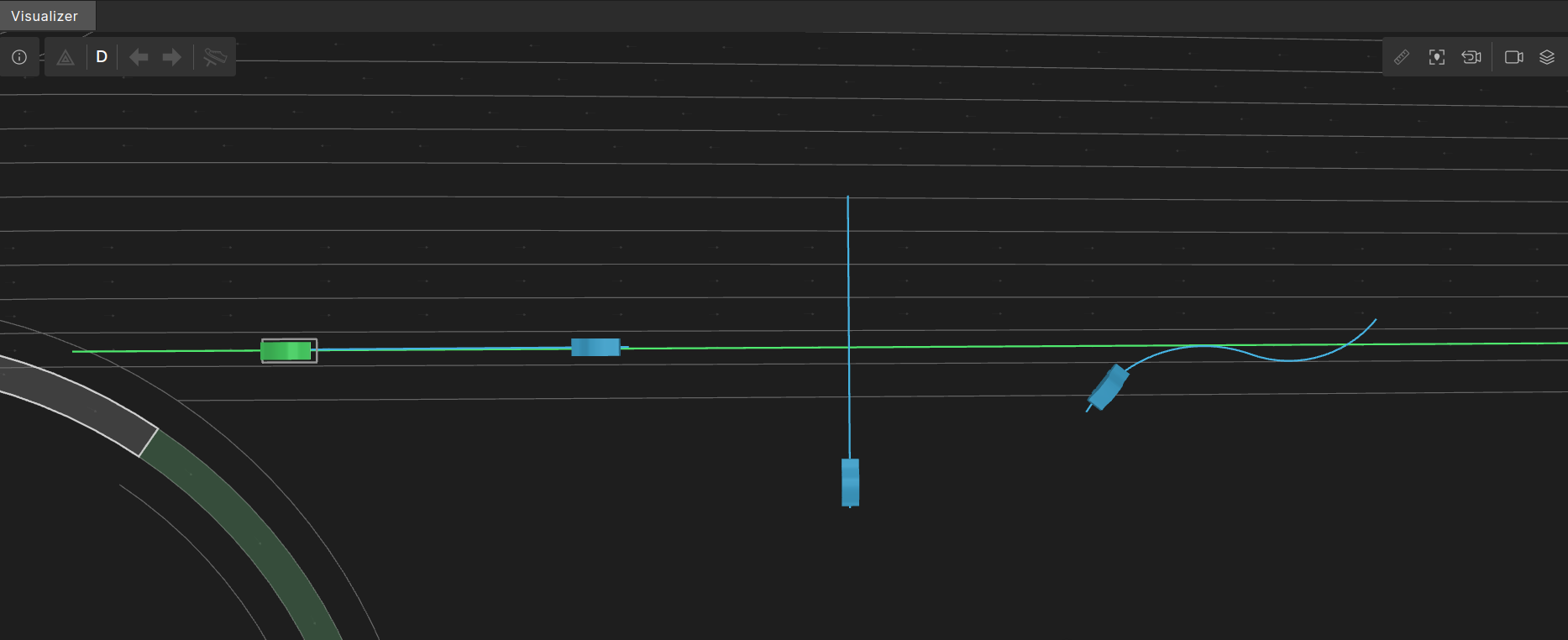
The image below shows NPC paths, in blue, on crossing_path occurrences corresponding to the three out-of-the-box basic patterns. From left to right:
oncoming- A forty meter straight line with heading of pi radians.traverse- A forty meter straight line with heading of pi/2 radians.s_curve- An 'S' shape made of two connected arcs.
OSC definition of crossing_path
# Intermediary struct for virtual route elements
# Concrete virtual route elements should inherit from this and not from road_element
struct virtual_road_element inherits road_element

struct crossing_path inherits virtual_road_element:
    # the id of the road_pattern for this crossing_path
    #
    kind: road_pattern_id
top.path_along_drive
The modifier top.path_along_drive places a crossing_path along a planned drive. When placing a pattern, its anchor point is placed at a calculated position and then the rest of the pattern is placed relative to the anchor point.
OSC definition of top.path_along_drive
modifier top.path_along_drive:
    cross_path: crossing_path with:
        properties(it, required: true)
    drive: any_scenario with:
        properties(it, required: true)
    lon_offset: length with:
        properties(it, required: true)
    lat_offset: length with:
        properties(it, required: false)
        keep(default it == 0m)
    rel_angle: angle with:
        properties(it, required: false)
        keep(default it == 0degree)
    force_on_road: bool with:
        keep(default it == false)
    flexiline_lateral_offset_kind: flexiline_lateral_offset_kind with:
        keep(default it == follow_by_lateral_offset)
Parameters
| Parameter | Description |
|---|---|
cross_path |
The crossing_path occurrence to place on the map. |
drive |
The drive along which to place the crossing_path. |
lon_offset |
A longitudinal offset in road coordinates along the drive. |
lat_offset |
A lateral offset relative to the drive route at the given lon_offset. |
rel_angle |
The rotation angle relative to the lane angle of the drive at lon_offset. The angle is added to the pattern’s heading, which is also relative to the angle of the lane of the drive at lon_offset. |
force_on_road |
If set to ‘true’, then the entire pattern must be located on the road surface. If that is not possible, then a solver failure error will be issued. |
flexiline_lateral_offset_kind |
This argument specifies how a lateral offset is applied to a flexibleLine geometry. It may have one of two values: move_by_lateral_offset or follow_by_lateral_offset |
move_by_lateral_offset
In move_by_lateral_offset the path follows the shape of the map route exactly and is moved laterally from the anchor point by the specified lateral offset. Depending on the shape of the route and the position of the anchor point, the offset pattern may cross the route

follow_by_lateral_offset
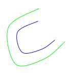
The value follow_by_lateral_offset is the default flexiline_lateral_offset_kind. Here, the path's reference line follows the map route with the specified lateral offset. This means that if the pattern follows a curve, then its length will increase when moved to the outer side of the curve, and decrease when moved to the inner side of the curve:
Syntax
path_along_drive(
    [cross_path:] <crossing-path>,
    [drive:] <any-scenario>
    [, lon_offset: <lon-offset>]
    [, lat_offset: <lat-offset>]
    [, rel_angle: <angle> ]
    [, force_on_road: <force-on-road>]
    [, flexiline_lateral_offset_kind: <flexiline_lateral_offset_kind>])
Example: Use patterns to simulate a NPC
This example shows how to use a pattern to simulate an NPC entering a road after turning left from a driveway.
Defining the pattern
- Starts with a vertical line (angle 1.5π radians) of length 15 meters.
- Followed by a quarter-circle counter-clockwise arc with a 10m radius (curvature is 0.1 and length 15.707963268 meters).
- Followed by a flexibleLine of length 100 meters and heading of 0 radians. I.e., 100 meters that follow exactly the route that they are placed on.
- The anchorOffset is very close after the beginning of the flexibleLine.
<?xml version="1.0" encoding="UTF-8"?>
<roadPattern>
    <header fileVersion="1" >
        <patternParameters anchorOffset="31" />
    </header>

    <planView>
        <geometry hdg="4.7124" length="15" width="3.6">
            <line/>
        </geometry>
        <geometry hdg="4.7124" length="15.707963268" width="3.6">
            <arc curvature="0.1"/>
        </geometry>
        <geometry hdg="0" length="100" width="3.6">
            <flexibleLine/>
        </geometry>
    </planView>
</roadPattern>
Scenario using a crossing_path with a registered pattern
In the scenario, we register the pattern and then use the modifier path_along_drive to position the crossing_path with the flexibleLine on the drive route of the SUT.
import "$FTX/env/basic/exe_platforms/model_ssp/config/model_dummy_config.osc"
import "$FTX/env/basic/msp/open_drive.osc"
import "$FTX/env/basic/road_patterns/ftlx_basic_patterns.osc"

extend test_config:
    set map = "$FTX/packages/maps/Town04.xodr"

# Add road_pattern_id enum value for the new road pattern.
#
extend road_pattern_id: [from_driveway_left]

# Register the new road pattern.
#
extend road_patterns_registry:
    def load() is also:
        register(from_driveway_left,
                "$FTX/qa/regression/user_docs_examples/osc/from_driveway_left_pattern.xml")

scenario sut.vehicle_exits_from_driveway:
    crossing_path: crossing_path with:
        keep(it.kind == from_driveway_left)

    road: one_way_road with:
        keep(it.length > 150m and it.max_lanes < 3)

    # position the crossing_path with the beginning of the flexible part (anchor) at offset 40m of road.
    #
    path_along_drive(crossing_path, drive: d, lon_offset: 40m)
    npc: vehicle
    do parallel(overlap:equal, duration: [20..40]second):
        serial:
            d: sut.car.drive() with:
                along(road)
        serial:
            npc.drive() with:
                # start_offset must be greater than half the npc length to avoid error
                # "Generated position is out of lane boundaries".
                #
                along(crossing_path, start_offset: 3m, at: start)
                x: along(crossing_path, end_offset: 0m, at: end)
                override(x, run_mode: best_effort)

extend top.main:
    do sut.vehicle_exits_from_driveway()
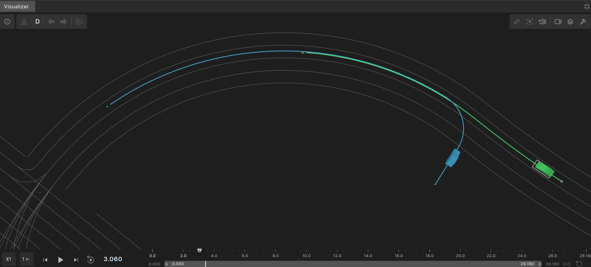
The image below shows the planned path of one random execution. The SUT’s planned path is marked in green and the NPC’s planned path is marked in blue.
top.path_along_route
The top.path_along_drive modifier places a crossing_path along the route of another route element. When placing a pattern, its anchor point is located at a calculated position, and the rest of the pattern is placed relative to that anchor point.
OSC definition of top.path_along_route modifier
modifier top.path_along_route:
    # Output properties

    # The resulting crossing path generated from defined input properties
    #
    cross_path: crossing_path with:
        properties(it, required: true)

    # Input properties affecting the position of the anchor point

    # Input 'road', used for defining the reference route
    #
    road: road_element with:
        properties(it, required: true)

    # Sets a longitudinal offset from the start of the road
    #
    lon_offset: length with:
        keep(lon_offset >= 0m and lon_offset <= road.length)

    # Sets the required lane index
    # lane-index is relative to the valid lanes in 'road',
    # 1 being the right-most lane in the road_element at the relevant lon_offset
    #
    lane_index: int with:
        keep(default it == 1)

    # Lateral offset from the chosen lane
    # The offset will be calculated according to the "lat_reference" type
    #
    lat_offset: length with:
        keep(default it == 0m)

    # Defines the reference line from which "lat_offset" is calculated
    #
    lat_reference: line with:
        keep(default it == center)

    # Rotation relative to the road at the calculated position
    #
    rel_angle: angle with:
        keep(default it == 0degree)

    # Force resulting position within lateral road boundaries
    #
    force_on_road: bool with:
        keep(default it == false)

    flexiline_lateral_offset_kind: flexiline_lateral_offset_kind with:
        keep(default it == follow_by_lateral_offset)
Parameters
| Parameter | Description |
|---|---|
cross_path |
The crossing_path occurrence to place on the map. |
road |
The route element occurrence along which to place the crossing_path. |
lon_offset |
A longitudinal offset along the route element occurrence. |
lane_index |
A 1-based index indicating the lane in the road at the longitudinal offset lon_offset, where 1 is the rightmost lane. |
lat_offset |
A lateral offset from the lane position indicated by road, lon_offset and lane_index. |
lat_reference |
The reference line from which the lat_offset is calculated, which can be left, right, or center. |
rel_angle |
The rotation angle relative to the angle at the lane position indicated by road, lon_offset, and lane_index. This angle is added to the pattern’s heading, which is also relative to the angle at the indicated lane position. |
force_on_road |
If set to ‘true’, then the entire pattern must be located on the road surface. If this is not possible, then a solver failure error will be issued. |
flexiline_lateral_offset_kind |
This argument specifies how a lateral offset is applied to a flexibleLine geometry. It may have one of two values: move_by_lateral_offset or follow_by_lateral_offset |
Example using from_driveway_left pattern
This example is the same as the previous example, but uses path_along_route instead of path_along_drive. We use the same from_driveway_left pattern, however this time we rotate the pattern 180 degrees. This results in the NPC coming out of the driveway and driving against traffic direction. The following graphic shows a possible outcome that may have the planned paths. The SUT path is in green and the NPC path is in blue.

Example scenario using from_driveway_left pattern
import "$FTX/env/basic/exe_platforms/model_ssp/config/model_dummy_config.osc"
import "$FTX/env/basic/msp/open_drive.osc"
import "$FTX/env/basic/road_patterns/ftlx_basic_patterns.osc"

extend test_config:
    set map = "$FTX/packages/maps/Town04.xodr"

# Add road_pattern_id enum value for the new road pattern.
#
extend road_pattern_id: [from_driveway_left]

# Register the new road pattern.
#
extend road_patterns_registry:
    def load() is also:
        register(from_driveway_left,
                 "$FTX/qa/regression/user_docs_examples/osc/from_driveway_left_pattern.xml")

scenario sut.vehicle_exits_from_driveway:
    crossing_path: crossing_path with:
        keep(it.kind == from_driveway_left)

    road: one_way_road with:
        keep(it.length > 150m and it.max_lanes < 3)

    # position the crossing_path with beginning of flexible part (anchor) at offset 40m of road.
    #
    path_along_route(crossing_path, road: road, lon_offset: 140m, rel_angle: 180degree)
    npc: vehicle
    do parallel(overlap:equal, duration: [20..40]second):
        serial:
            d: sut.car.drive() with:
                along(road, start_offset: 0m, at: start)
        serial:
            npc.drive() with:
                # start_offset must be greater than half the npc length to avoid error
                # "Generated position is out of lane boundaries".
                #
                along(crossing_path, start_offset: 3m, at: start)
                x: along(crossing_path, end_offset: 0m, at: end)
                override(x, run_mode: best_effort)

extend top.main:
    do sut.vehicle_exits_from_driveway()