Foretify’s coordinate system
Foretify handles data related to the position of an object using one of three different coordinate systems, depending on the context:
-
The Global System, also known as earth-fixed axis system, defines position in relation to an arbitrary point on the map that is loaded for a particular test. Foretify uses this system when communicating with external components such as a simulator or a System Under Test (SUT).
-
The Road/Lane System defines position in relation to the centerline of a referenced lane in a road on the loaded map. Foretify uses this system when calculating the longitudinal or lateral distance between positions on a road.
-
The Local System defines position in relation to a referenced object’s position at rest. Foretify uses this system when calculating a position in relation to the position of a referenced object.
The definition of these three systems is based on the ISO 8855 standard. These systems, like most coordinate systems, follow the right-handed rule for curve orientation. This means that motion around any axis is counter-clockwise, as opposed to left-hand systems where that motion is clockwise. Thus, curved motion is defined in all three systems using the following convention:
-
Positive curvature is a left curve (counter-clockwise motion)
-
Negative curvature is a right curve (clockwise motion)
In order to correctly position objects in a scenario or to correctly interpret data captured by trace, coverage, or checks or returned by external methods, you need to understand these coordinate systems.
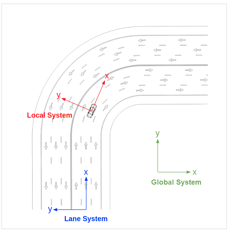
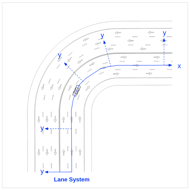
Figure 1 shows a graphical comparison of the three systems. Take note of the following:
-
The origin point of the Global System is on the map but not necessarily on a road or lane.
-
The Road/Lane System takes into account the geometry of the road or lane, so an object positioned along the X axis of the origin point remains in the center of the lane even as the lane curves to the right.
-
The Local System does not take into account the geometry of the road or lane, so an object positioned along the X axis of the origin point (the referenced object, shown here as a vehicle) is not necessarily in the lane or even on the road.
The Global System
The Global System defines position in relation to an arbitrary point that is defined by the loaded map. Foretify uses this system when communicating with external components such as a simulator or a SUT, so any data stored or calculated externally and returned by an external agent or method is defined in this system. All Simulator Support Package (SSP) and SUT Support Package (DSP) APIs use this system.
Global System: Definition of axes
The X and Y axes are parallel to the ground plane and the Z axis points upward. When used within a geographic reference, the following convention applies:
-
X - East
-
Y - North
-
Z - Up
Global System: Origin point
The origin point for the system is arbitrary and defined by the loaded map.
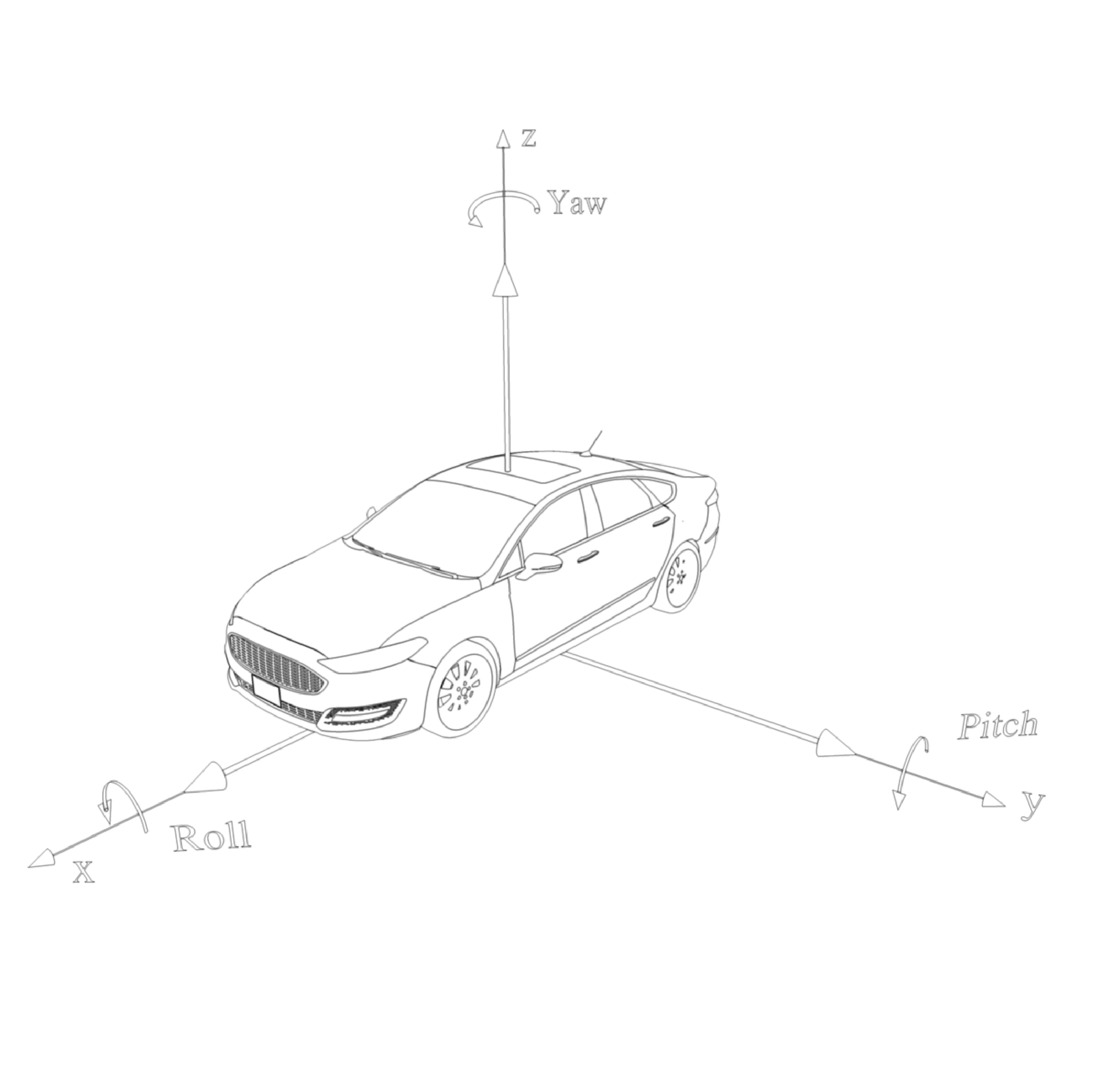
Global System: Angles
-
Yaw - around the Z axis, 0.0 = forward, counterclockwise
-
Pitch - around the Y axis, 0.0 = level (in the X/Y plane)
-
Roll - around X axis, 0.0 = level (parallel to the X/Y plane)
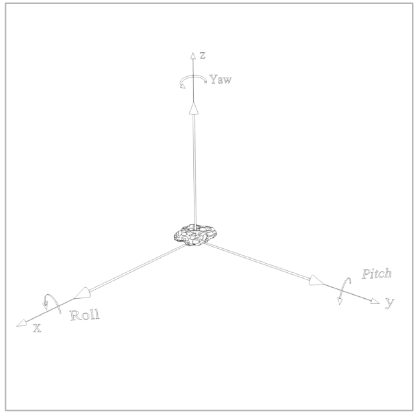
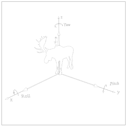
Figures 2 - 4 show how this system is applied to various types of target objects.
Global System: Example usage
Using the three coordinates and the three rotation angles of this system, Foretify specifies the precise position and orientation of an actor. You can see these global coordinates when tracing, for example, a vehicle’s state.
[INFO] [TRACER] [0.020] trace:
car1.state.msp_pos.global_position.coord.x=-693.678
car1.state.msp_pos.global_position.coord.y=338.14
car1.state.msp_pos.global_position.coord.z=0
car1.state.msp_pos.global_position.rotation.roll=0
car1.state.msp_pos.global_position.rotation.yaw=13.20
car1.state.msp_pos.global_position.rotation.pitch=0
The Road/Lane System
The Road/Lane System defines position in relation to the centerline of a referenced lane in a road on the loaded map. Foretify uses this system when calculating the longitudinal or lateral distance between positions.
Road/Lane System: Definition of axes
-
X - a position along the centerline, measured from the beginning of reference lane
-
Y - the lateral position perpendicular to the lane centerline at the longitudinal position X
Note
The definition above applies to both right-hand and left-hand traffic modes. When writing traffic-mode agnostic code, use the OSC2 helper functions curb_side() and center_side() to refer to the logical road side.
Road/Lane System: Origin point
-
The origin point of the longitudinal axis (X) is defined as the initial logical lane centerline.
-
The origin point of the lateral axis (Y) is defined according to the position on the longitudinal axis.
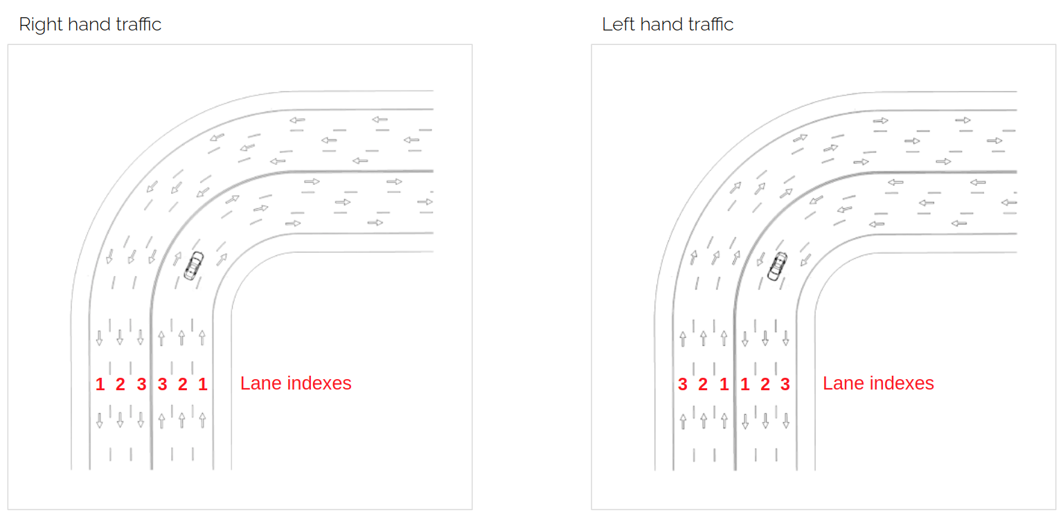
Road/Lane System: Lane indexes
Lane indexes are numbered from right to left according to the road direction. The counting for the rightmost lane starts from 1. This applies to both right-hand and left-hand traffic modes.
Road/Lane System: Example usage
The distance() scenario modifier uses the Road/Lane System to specify a distance to be traveled during a drive along the X axis (the centerline of a referenced lane).
do serial()
    d1: car1.drive() with:
        distance([30..50]m)
The Local System
The Local System defines position in relation to a referenced position or target object. Foretify uses this system when calculating a position in relation to a target object.
Local System: Definition of axes
-
X - Forward, parallel to the target object’s longitudinal plane
-
Y - Left, perpendicular to the target object’s longitudinal plane
Local System: Origin point
The origin point is defined as the center point of the bottom plane of the target object’s bounding box.
Local System: Example usage
The at_offset_local() modifier uses Local System coordinates to place an object such as a rock or a person in relation to a target vehicle. Depending on the lateral offset, the placed object might or might not be in the lane of the target vehicle.
scenario sut.person_on_path:
    ref_drive: any_scenario
    person: person
    position: msp_position

    # Specify a position along a drive
    position_along_drive(position, ref_drive,
      path_fraction: [10..100], lat_offset: [-3..3]meter)

    do serial:

        # Place a person at the specified position
        person.exists_at(position.at_offset_local(0m,0m,2m)) with:
          rotation(yaw: [80..100]degree])